
Crow CS-47 Link Manuel utilisateur

1
ELECTRONIC ENGINEERING LTD.
TEL : + 972 3 556 99 37 FAX: + 972 3 559 29 81
www.thecrowgroup.com
CS47 GSM PHONE LINE BACKUP
User Guide V1.00
REV. A SOFTWARE VERSION 1 12/07/04

2
INTRODUCTION ..................................................................................................3
General Specification: ...........................................................................................3
Basic Functionality................................................................................................3
Reduction of Costs................................................................................................3
Password Protection .............................................................................................4
Operation.............................................................................................................4
SMS support.........................................................................................................4
Inputs...................................................................................................................4
Outputs ................................................................................................................4
SIM card...............................................................................................................4
Connecting the CS-47 ...........................................................................................5
CS-47 PC software ...............................................................................................6
Translations..........................................................................................................6
Software installation ..............................................................................................6
Configuration of the CS-47 unit ..............................................................................7
Configuring system inputs......................................................................................8
Defining Input Telephone Numbers ........................................................................8
Defining SMS Messages for Inputs.........................................................................9
Configuring System Outputs ................................................................................10
Defining Output Parameters.................................................................................10
Triggering the System .........................................................................................11
Configuration of the miscellaneous page ..............................................................13
Configuration of the “ low power” message : .........................................................13
Configuration of the “Test message” area .............................................................13
Configuration of the “phone line ” area..................................................................14
Add prefix number...............................................................................................15
Communication page ..........................................................................................16
cellular dial prefix ................................................................................................16
communication with the unit.................................................................................16
File Options ........................................................................................................17
Using the CS47 after it was installed ....................................................................18
Sending SMS Messages .....................................................................................18
Output operation by SMS....................................................................................18
Activating and Deactivating the System................................................................19
Changing the User Password ..............................................................................19
Handling Received SMS Messages......................................................................19

3
1INTRODUCTION
The CS-47 is a cellular backup to PSTN phone line system.
When connected to an alarm control panel, the CS-47 operates as a GSM
back up unit to a PSTN line, enabling to re-direct incoming and outgoing
calls to the GSM network in case of regular phone line failure.
1.1General Specification:
•Built-in Tri-Band GSM transceiver
•Continuous PSTN line supervision
•GSM backup at PSTN Line failure
•Programmable SMS messages
•Multi language support for SMS and for PC graphical interface
•4 inputs for SMS and output operation
•4 outputs operated either locally or by SMS
•Battery backup support including charger
•Status report by SMS messages
•Cheaper call routing to GSM when dialing to a cellular number
1.2Basic Functionality
The Mobile Bridge provides operators the means to connect to various
inputs and output devices. It uses cellular technology to send and receive
messages, allowing operators to monitor and control the required devices.
For example, the Mobile Bridge sends an SMS to the security center if an
office has been entered without authorization.
1.3Reduction of Costs
With the CS-47, all telephone landlines (PSTN) are routed through the
CS-47 unit, together with the cellular modem that is connected to the CS-
47. Certain telephone calls are then routed through the CS-47 modem. This
reduces costs on these telephone calls, because the System automatically
selects the least expensive route and diverts calls to either the landline or
the cellular line, as relevant. The switch is according to a programmable
prefix number, when the unit detects this prefix number that was
programmed it switches the call to the cellular line although a PSTN line is
connected.

4
1.4Password Protection
The Mobile Bridge uses two different kinds of passwords to ensure System
Security:
Program password–allows users defined as System Administrators to
access the configuration program and change the System configuration as
required.
This password is not available to end-users.
User password –used in SMS messages by end-users to trigger various
events for the input and output devices defined in the System.
Both passwords must consist of four characters
1.5Operation
The system powered by 14VDC with a 12V/1.3A backup battery. The
battery is recharged by the system.
1.6SMS support
The CS-47 support programmable SMS messages, the messages are
programmed by Crow PC software and downloaded to the system by a D-
Link cable. The system support multi language SMS messages
1.7Inputs
The CM-18 offers 4 digital inputs. Every input trigger generates an SMS
message to a programmed number and activates an output.
1.8Outputs
The CS-47 has 4 programmable outputs. 4 open drain FET outputs, output
number 1 is also a dry contact relay in parallel. The outputs can be
operated locally according to inputs triggering or by SMS ( by remote).
1.9SIM card
The CM-18 supports 1.8V / 3V / 5V SIM cards. Before entering a SIM card
to the CM18 the pin code should be cancelled for that SIM card, you can
cancel the pin code using any kind of mobile phone.
5
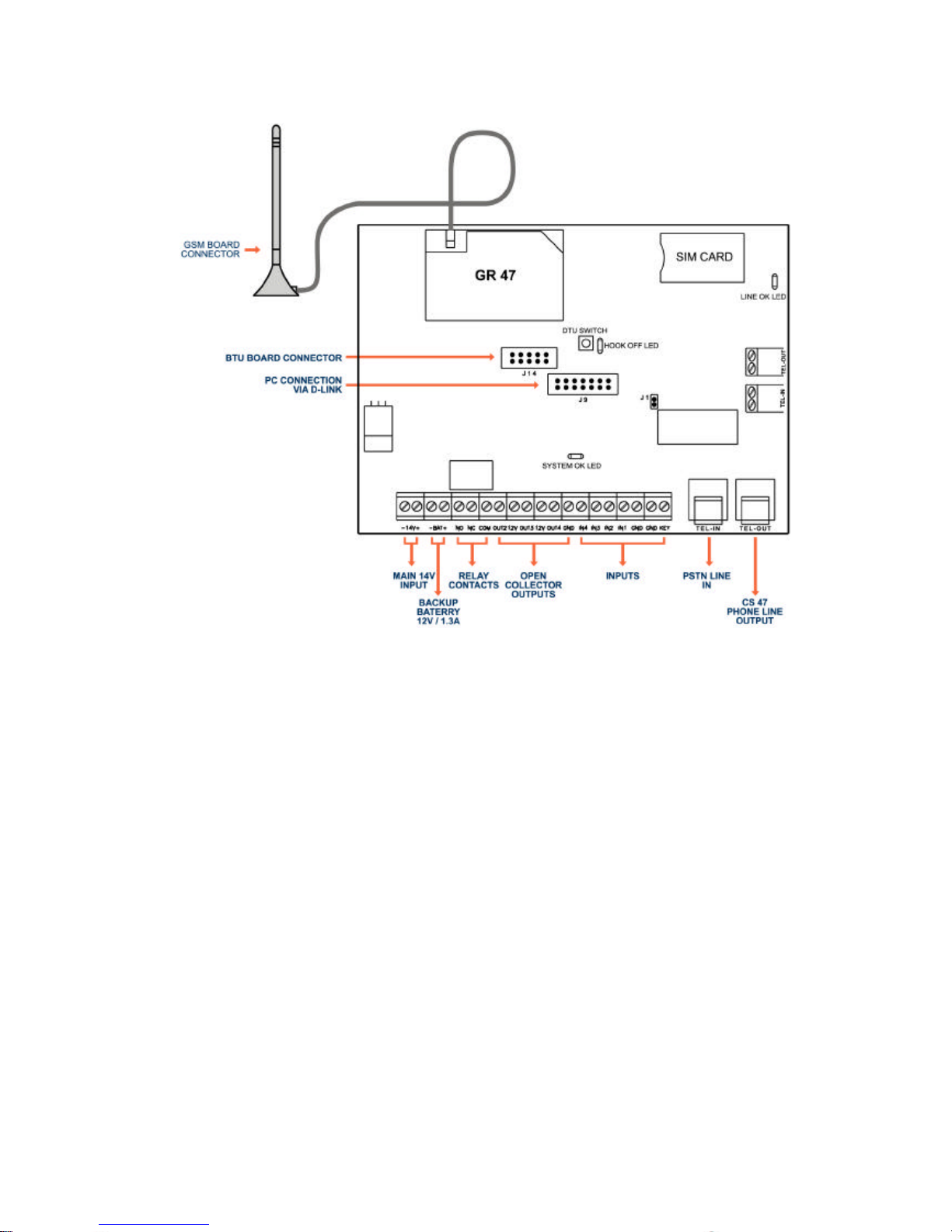
2Connecting the CS-47
TEL-OUT: phone line output supplied to an external system, RJ11
connector or terminal block
TEL-IN: PSTN phone line input (main phone line), RJ11 connector or
terminal block
Main power supply: 13.8 VDC supplied by external power source or panel
Battery: 12V / 1.3A
Antenna: dual band GSM antenna.
Inputs: 4 digital inputs and a key input, in order to trigger an input you need
to pull the input low (connect ground)
Outputs: 4 digital open drain outputs and a dry contacts relay ( the relay is
in parallel to output 1).
Indication LED’s
System OK led –blinking when the system is ready for use
Hook off led: the led is “on” when the external system picks up the phone
(goes off hook).
Line OK led –light when PSTN line exists.

6
3CS-47 PC software
The CS-47 PC software is a graphical user interface (GUI) to be used in
order to configure the unit.
3.1Translations
The GUI can be translated to various languages, the text and the tool tip
box can be translated by translating the texts in two files in the software
folder:
“:\Program Files\CS47”.
The files to be translated are frmedit.txt and frmEditToolTip.txt.
3.2Software installation
To install the configuration program, perform the following steps:
1. From the CD that comes with the CS47 package, double-click the setup
file.
2. Follow the steps in the setup wizard to select the required location on the
local hard drive.

7
Configuration of the CS-47 unit
The configuration of the CS-47 can be in 3 different ways:
1.Local configuration –using crow graphical interface (PC
software), connecting via D-link cable
2.Local configuration –using crow DTU board, in order to use
the DTU board the configuration must be load to the board
before the installation from a programmed CS47 unit
3.Remote configuration –using a cellular modem with sim card
in the same network, the tool for the configuration is the PC
software.
Graphical User Interface
The graphical user interface of the Mobile Bridge configuration wizard
consists of one window with four tabs, each containing parameters to
configure various options. The tabs are as follows:
Input –Use to configure up to four System inputs.
Output –Use to configure up to four System outputs.
Miscellaneous –Use to configure general System parameters.
Communication –Use to select the telephone dialing prefixe that will be
recognized by the System, for least cost call routing, and for communicating
with the unit.
Each tab contains a number of areas. For example, the Input tab contains
an area to select a specific input, an area to define the phone numbers that
will receive SMS messages about the input, and an area to define the
messages themselves

8
3.3Configuring system inputs
3.3.1Defining Input Telephone Numbers
The Mobile Bridge allows the definition of up to four telephone numbers per
system input. SMS messages concerning the state of the relevant input are
sent to these numbers.
To define the telephone numbers for each input, perform the following
steps:
1. Click theInput tab.
2. From the Input Number drop-down list, select the desired input number.
3. Select theEnable checkbox next to each telephone number that will be
used.
4. In the Phone Number area, enter the telephone numbers that will
receive
SMS messages for the relevant input number.
Note: Click Copy Phones to copy these phone numbers to all other
telephone input fields, for use with other inputs.

9
3.3.2Defining SMS Messages for Inputs
The Mobile Bridge allows the definition of different SMS messages to be
sent,
depending on the state of the input. For this reason,the Message area of
the Input
window contains two Message fields.These fields correspond to the two
possible states of an input, which are as follows:
•On –The input device is running (the input has changed from
“high” to “low”)
•Off –The input device is not running (the input has changed
from “low” to “high”)
To define the SMS messages to be sent for each input state, perform the
following steps:
1.Click the Input tab.
2.In the Messages area, select theEnable checkbox for each state for
which a message is to be enabled.
3.In the Message field corresponding to the enabled state, enter the SMS
message to be sent.
Note: The Chars Left field displays the permitted number of characters
remaining for each message. This is a read-only field.
4.Define the Detect time (in seconds) for the message. The Detect time is
the amount of time an event must continue in order to trigger the SMS.
5.Define the Delay time (in seconds) for the message. The Delay time is
the amount of time it takes to trigger the SMS after an event has occurred.
6.Define the Repeat time (in minutes) for the message. The Repeat time is
the interval at which the SMS is re-sent, if the status of the input does not
change.
7. In case you need an output to be activated on an input triggering choose
an output number (one of the outputs).

10
3.4Configuring System Outputs
The CS-47 allows the configuration of up to four output devices. The
configuration procedure for each output device includes defining the normal
status of each device.
An output can be activated in two different ways:
Locally –activate an output when an input is triggered. defined in the input
page
By SMS –activation of an output by remote using SMS messages.
Selected when enabling the checkbox in the output page.
Note: if one of the option selected than the other option is disabled.
3.4.1Defining Output Parameters
Defining the output parameters includes enabling or disabling each device,
and defining the normal state of each. This tab also allows the System
Administrator to change the user password, if necessary.
To define output parameters, perform the following steps:
1.Click the Output tab.
2.To change the user password, enter the new password in the User
Password
field.
Autres manuels pour CS-47 Link
1
Ce manuel convient aux modèles suivants
1
Table des matières
Autres manuels Crow Accessoires


