coolbreeze CB4900 Manuel utilisateur
CB4900 / CB6600 Spot Cooler
USER’S MANUAL

HEPHZIBAH CO.,LTD.
423-5 CHUNGCHUN-DONG, BUPYUNG-KU
INCHEON, KOREA
TEL : +82-32-509-5834
FAX : +82-32-502-5519
Website : www.airrex.co.kr
WARRANTY
AIR CONDITIONERS give more reliable performance, comfort and durability the
more they are used. They are built under a strict quality assurance regime which
includes inspection both during and after production and exhaustive reliability
testing.
In the unlikely event you have any problems, please contact your dealer or
distributor. If the problem is as a result of a production fault or failure, repairs will
be undertaken free of charge during the period of warranty subject to the
following warranty conditions:
1. The warranty period is 12 months from the date of first purchase.
2. If the problem has been caused by customer error or misuse, abuse or
damage, then all repairs will be charged for.
3. This warranty applies to the Australia / New Zealand.
4. Proof and date of purchase must be supplied.
5. Please complete the details below and keep this warranty in a safe place.
6. All transport charges back to the dealer are at the customers cost. Keep all
original packaging to facilitate return. Return to customer will be at dealers cost
(if genuine warranty claim).
(Applicable to first retail purchaser only)
DESCRIPTION AIR CONDITIONER
MODEL CB4900 / CB6600
DATE OF PURCHASE
PRODUCT
SERIAL NO:
Warranty Period
( ) Months
Name of Company
Telephone No.
DISTRIBUTOR
Name :
Address :
Telephone :
Cool Breeze Rentals
1300 885 188
12

2
TABLE OF CONTENTS
3
5
5
5
6
7
7
8
9
10
11
12
13
14
15
■SAFETY NOTES
■DESCRIPTION
·Front View
·Back View
·Control Panel
■OPERATING INSTRUCTIONS
·On/Off Operation
·Selection of Area/Room or Spot Cooling
·Temperature Control
·Off Timer
·Indicator and Operational Error Alerts
■CLEANING AND MAINTENANCE
■TROUBLE SHOOTING
■ACCESSORIES
■ SPECIFICATION
■WARRANTY 16

3
SAFETY INSTRUCTIONS
The following instructions are for ensuring the user’s safety and to prevent any physical injury or
material damage. Please read carefully and follow all instructions.
There are two sections to these instructions: WARNING and CAUTION.
Use a 230V. 50Hz. 1 phase power supply only.
(Wrong supply may cause a fire and / or shock hazard)
Securely plug into an earthed supply.
(Unless earthed, may cause electric shock)
Do not use a damaged power cable, plug or socket.
(Short, fire or shock hazard)
Do not remove plug by pulling cable or with wet hands.
(Risk of fire and electric shock)
Before cleaning, remove plug from socket.
(Otherwise risk of electric shock)
Do not place anything on top of the machine.
(This could cause electric shock, malfunction or injury)
Do not use an extension lead unless of the approved type.
(Heavy duty, Risk of fire and / or electric shock)
Ensure mains plug is clean and securely plugged in.
(Otherwise it may short causing smoke and fire)
Ensure correct (13 amp) fuse is fitted in the plug.
(Otherwise malfunctioning or fire may result)
Do not ‘kink’ or sharply bend the power cable nor put any weight on it.
(The insulation may be damaged causing fire and/ or electric shock)
Do not turn off by removing power plug. Always turn off at control panel first.
(Risk of electric shock and / or malfunction)
Do not use this cooler on unstable or inclined surfaces. Always use on solid flat floor.
(Risk of falling causing injury, fire or malfunction)
WARNING
The following symbols are for your guidance:
= You must NOT . = You MUST .
Keep this manual in a visible location near the cooler
for easy reference.

4
SAFETY NOTICE
GENERAL ADVICE BEFORE USE
·Ensure the safety of the location in which cooler is to be used.
·Ensure the floor or ground is smooth and sound.
·Ensure you allow at least 50cm air space all around the cooler.
·When in position LOCK the casters to prevent rolling.
·Never use the cooler at more than 2° incline
FOR MAXIMUM EFFICIENCY
·In airtight areas use vertical exhaust into ceiling.
·If possible locate exhaust outlet through a window or door to outside.
·Exhaust ducting should be no longer than 2m for maximum efficiency.
·Ensure correct electricity supply.
CAUTION
Do not place cooler on uneven, unstable or inclined surface.
(This could cause malfunction)
When storing the cooler, ensure that it is kept in a dry, cool place.
(To prevent corrosion and malfunction)
If not being used for some time or if lightening is present, always unplug from mains.
(To prevent risk of electric shock, short circuit or fire)
Do not spray water on to the cooler nor use solvents such as benzene, thinner or
alcohol for cleaning.
(There is a risk of electric shock and / or short circuit)
If the power cable is damaged this must be replaced by a fully qualified electrician.
(To avoid danger of electric shock, short circuit or fire)
5
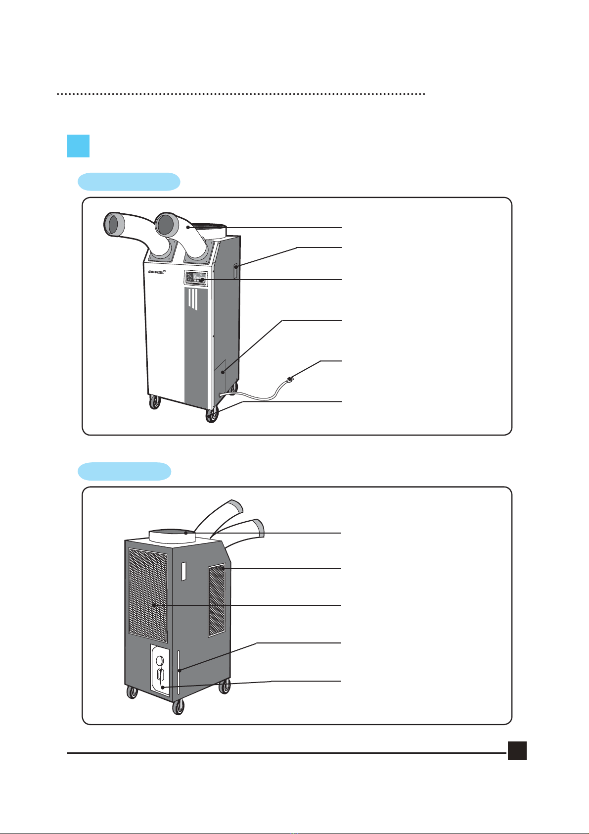
EXTERIOR DESCRIPTION
FRONT VIEW
BACK VIEW
FLEXIBLE DUCT OUTLET (COLD AIR)
HANDLE
DIGITAL CONTROLLER
CONDENSER OUTLET (HOT AIR)
EVAPORATOR FILTER
AMBIENT AIR INTAKE.
CONDENSER FILTER
CASTERS (FRONT LOCKABLE)
ELECTRIC PANEL
(ACCESS BY AUTHORISED SERVICE
PERSONNEL ONLY)
POWER PLUG
WATER LEVEL INDICATOR
TO CHECK WATER LEVEL OF THE
CONDENSATE TANK.
CONDENSED WATER TANK
TO COLLECT WATER GENERATED
DURING COOLING.

6
CONTROL PANEL FUNCTIONS
① Power : Use to power On / Off.
② : Raises or lowers temperature and/ or sleep (off) time.
③ Cool : Use to select cooling mode.
④ Low Mode : Controls fan low speed.
⑤ High Mode : Controls fan high speed.
⑥ Off Timer : To set the length of time, once turned on, that you wish the
cooler to run for. You can set 0~24 hours. Time intervals are
30mins. up to 10 hours and then 1 hour between 10 and 24 hours.
⑦ Remote : From the long distance, you can control the machine by wired remote control.
⑧ Room : If the LED is On, the displayed temperature is for Room temp. If the LED
is Off, the displayed temperature is for spot temp.
⑨ Comp. : When the compressor is operating, the LED is On.
⑩ Error : Error signal ( E1 : High Pressure, E2 : Low Pressure, E3 : Sensor, AF: Eva Freezing)
⑪ Water Full : Red light indicates ‘Tank Full’. The compressor will shut off
automatically. Empty tank and replace in position to resume operation.
⑫ Align Drain Tank : The red light indicates the water tank is not in the correct position.
⑬ Display : Display Room/Spot temperature, and the setting temp and sleep time in case of
setting them. When the user set the sleep timer, ‘hr’ will be turned on.
(Display of 'LO' : under the 0℃, Display of 'HI' : over the 50℃)
⑤
①
②
③④
⑦
⑧
⑩
⑪
⑫
⑬
⑨
⑥

7
OPERATION
RUNNING & STOP
1. START BY PRESSING THE ‘POWER’ BUTTON.
·Cooler will start up automatically.
·To STOP the unit, press the ‘POWER’ button once again.
2. To change fan speed, press the ‘Low’ button.
3. If you wish to operate on fan only, press the ‘COOL’ button. To resume cooling,
press the ‘COOL’ button again.
(Note : There is a 3 minute delay when switching functions to protect the compressor)

8
SELECTION of AREA/ROOM or SPOT COOLING
To reduce the temperature of the entire room then select ‘Room/Area Cooling’.
For ‘targeted’ cooling of machinery, servers, or people etc. select ‘Spot Cooling’.
1. IF YOU WANT TO DISPLAY ROOM
TEMPERATURE, PUSH COOL AND BUTTON
SIMULTANEOUSLY FOR THREE SECONDS.
2. IF YOU WANT TO SWITCH FROM CENTIGRADE TO
FAHRENHEIT - PUSH (UP) AND (DOWN) BUTTON
SIMULTANEOUSLY FOR 3 SECONDS.

9
TEMPERATURE CONTROL OPERATION
1. When power is on, the set temperature is displayed.
Default of set temperature is 5℃.
2. When you push either (up) or (down) button, the
setting temperature can be changed.
3. The display showing the set temperature will
blink 3 times.
4. Limits of Room/Spot and Setting temperatures.
Room/Spot Temp. Setting range
0℃ - 50℃ 1℃ - 30℃
Cooling operates when
Room/Spot temperature is more than set
temperature.
Cooling stops when
Room/Spot temperature is less than set
temperature.
Ce manuel convient aux modèles suivants
2
Table des matières


