ClimateWorx 11 Series Manuel utilisateur

Series 11, Ceiling Units
Installation Manual
.cnIlanoitanretnIxroWetamilC
S11-IM2019 14 Chelsea Lane, Brampton, Ontario, Canada L6T 3Y4

Series 11 Installation Guide
S11-IM2019
2
Table of Contents
Table of Contents ................................................................................................................. 2
Site Preparation .................................................................................................................... 3
Location Consideration ....................................................................................................... 3
Positioning of Indoor units.................................................................................................3
Hanging the Unit................................................................................................................4
Positioning of Condensers or Condensing Units ...............................................................5
Positioning of Remote Controller Unit ..............................................................................6
Positioning of Remote Temperature/ Humidity Sensor......................................................6
Electrical Installation ........................................................................................................... 7
Power Feeding ...................................................................................................................7
Interconnecting Wiring ......................................................................................................7
Piping Connections ............................................................................................................... 8
Recommended Pipe Size for Remote Condensing Units.....................................................9
Recommended Pipe Size for Remote Condensers ............................................................10
Consult Factory for additional distances ..........................................................................10
Evacuation........................................................................................................................10
Fan Speed Control System ................................................................................................ 11
Head Pressure Control System ......................................................................................... 12
Operating the Thermostat ................................................................................................. 14
Dimensional Details ............................................................................................................ 17
Appendix A: Dimensional Drawings ................................................................................ 18
Appendix B: Electrical Schematic Drawings ................................................................... 33
Appendix C: Piping Schematic Drawings ........................................................................ 48
Series 11 Installation Guide
S11-IM2019 3
Site Preparation
In order to maximize operating efficiency and performance, the following areas should be observed at the
site-planning stage:
- The room should be surrounded with a vapor seal to eliminate moisture migration through the
building structure. Windows should be sealed and at least double-glazed to prevent sweating. All
door jams should fit tightly and should not have any grilles in them. Polyethylene film type ceiling,
vinyl wallpaper or plastic based paint on the walls and slabs are recommended to minimize
absorption and transmission of moisture into the room.
- Owing to a generally small population, a typical room should have fresh air kept at only about 5% of
the re-circulated air. This provides enough ventilation for personnel and pressurizes the room to
prevent dust from entering through leaks. The incoming fresh air must be filtered very closely, and
preferably pretreated. Otherwise heating, cooling, humidifying and dehumidifying loads of the
incoming fresh air should be taken into account in determining total loading requirements.
Location Consideration
Positioning of Indoor units
The Series 11 unit is designed for ceiling mounting in or above a suspended T-bar ceiling grid. Care
should be taken to ensure that the supply and return air-paths are not blocked by equipment; preferably
the unit should be located over a clear floor space for ease of service. Additionally the units contain water
and as a result should not be mounted above equipment that could be damaged by water. It is
recommended that a field supplied drain pan complete with drain be installed beneath ducted units and all
water and glycol condensing units / condensers.
The unit should be mounted in such a way that the side panels can be easily accessed through the
surrounding ceiling tiles for service.
For spot cooling units (fully packaged) care should be taken in orienting the air grille supplied. The filter
grille (return air to the unit) should be located under the evaporator and the three way grill located under
the supply air section. The louvers on the supply air grill should be directed away from the return air to
avoid short circuiting of air.
The unit should be mounted above the flange of the T-Bar ceiling grid using the foam insulation provided
with the grille to seal to the bottom of the unit. Adjusting Fan Speed with M52 on grille supply/ return
models. For thermostat or ducted applications air balancing is required to adjust for correct fan speed.
Model 11XX15 11XX20 11XX25 11XX30
Standard Air Volume CFM 750 950 1100 1400
Cooling Max % 43 51 57 71
Idle Air Volume CFM 490 620 715 910
Cooling Min % 29 36 41 49
Series 11 Installation Guide
S11-IM2019
4
Hanging the Unit
Before hanging the unit, ensure the mounting surface is capable of supporting the unit’s weight. Refer to
Table 1 for unit weights.
Model 1 Ton
(Weight lbs)
1.5 Ton
(Weight lbs)
2 Ton
(Weight lbs)
2.5 Ton
(Weight lbs)
3 Ton
(Weight lbs)
4 Ton
(Weight lbs)
5 Ton
(Weight lbs)
Ai
r
-cooled self contained 235 240 245 250 N/A N/A N/A
DX Ai
r
-cooled 175 180 185 190 230 475 490
Air Handlin
g
Uni
t
110 110 110 110 140 415 430
Wate
r
-cooled self-contained 215 220 225 230 275 545 560
Gl
y
col-cooled self-contained 215 220 225 230 275 545 560
Chilled wate
r
110 110 110 110 140 415 430
Dual Cooled CW+CW N/A N/A N/A N/A N/A 515 530
Dual Cooled CW + DX Ai
r
N/A N/A N/A N/A N/A 575 590
Dual Cooled CW + DX Wate
r
N/A N/A N/A N/A N/A 645 660
Dual Cooled CW + DX Gl
y
col N/A N/A N/A N/A N/A 645 660
Free Coolin
g
N/A N/A N/A N/A N/A 665 680
Table 1: Unit Weights
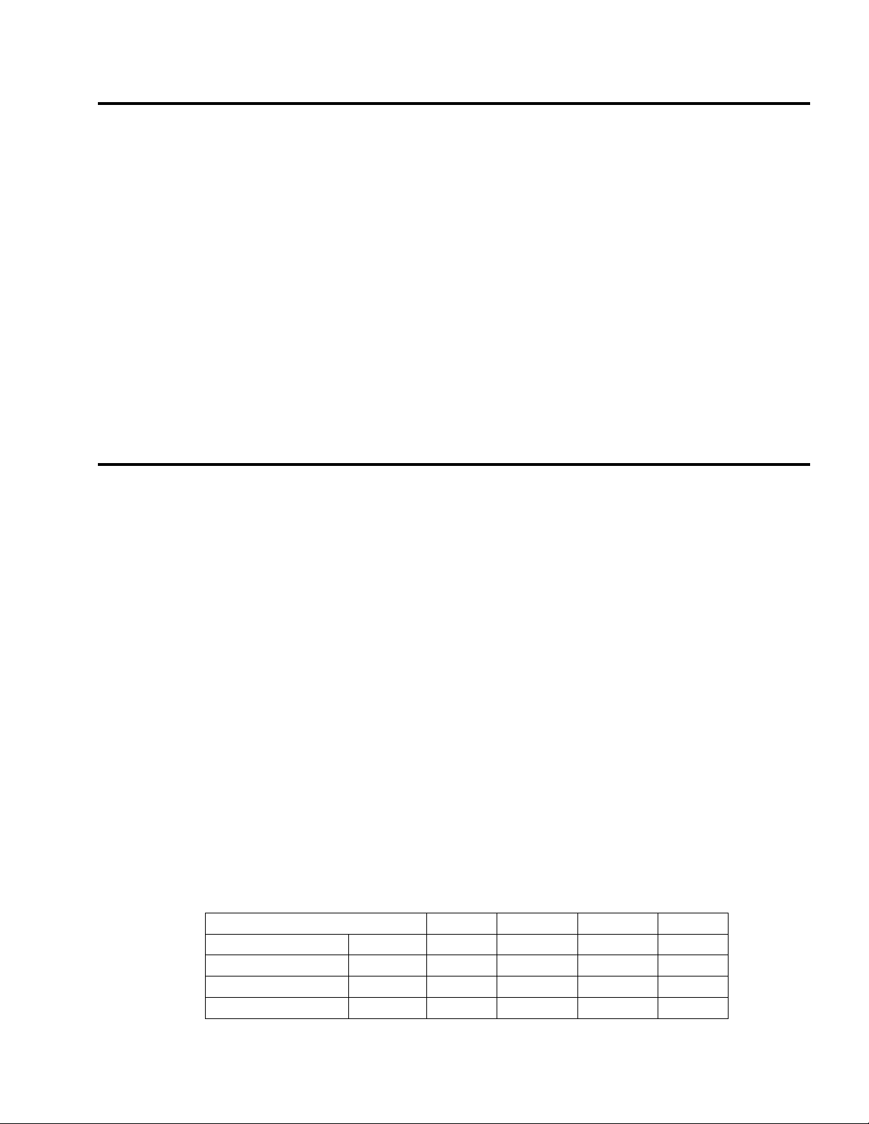
Attach the corner brackets to the corner posts of the
unit. Remove all the access panels and lift the unit into
the selected position. Using threaded hanging rod (3/8”
diameter) secure the unit in place using nuts and
washers (all field supplied).
For units supplied with vibration isolating spring
mounts place spring under corner bracket and attach
locking hardware. After hanging the unit, adjust spring
tensions to level the unit, shown in Figure 1.
Figure 1
Series 11 Installation Guide
S11-IM2019 5
Positioning of Condensers or Condensing Units
Condensing units should be located as close to the indoor unit as possible. From a security and
environment standpoint, outdoor air-cooled condensing units should be installed away from public access
and occupied spaces where low ambient sound level is required. Indoor air-cooled condensers or
condensing units should be located in areas where normal unit operating sound will not disturb the
working environment. Water and glycol condensing units should not be located above sensitive
equipment that could be damaged by water.
In order to avoid air short circuiting and inter unit re-circulation, air-cooled condensing units/condensers
should be located at least 1m (3 ft.) away from any walls, obstructions or adjacent units. To ensure
maintenance-free operation, air cooled condensing units/condensers should be located away from the
areas that are continuously exposed to loose dirt and foreign materials that may clog the coil.
Indoor condensing units / condenser should be hung following the procedure outlined earlier. Outdoor
units should be firmly secured on steel supports or concrete plinths.
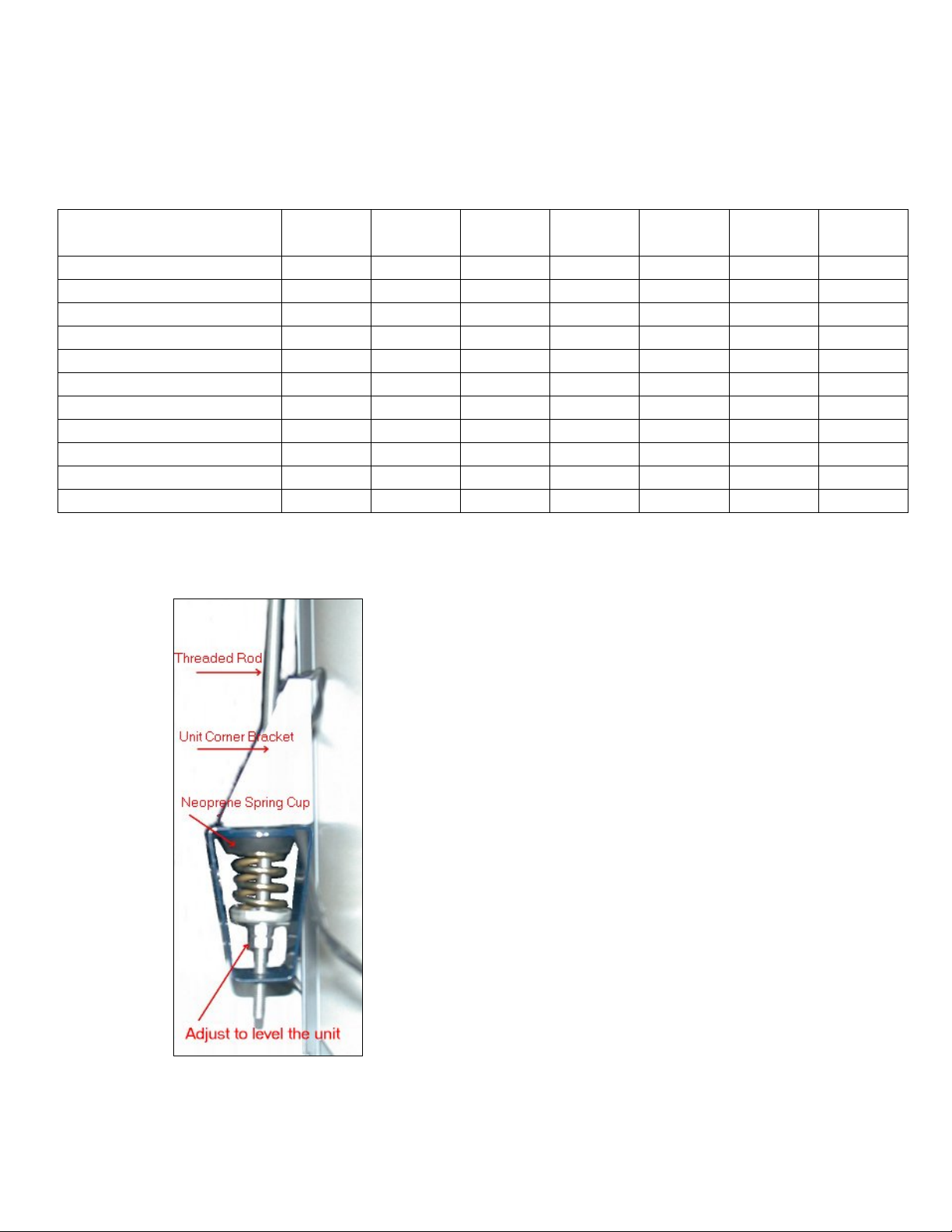
For packaged units the condenser fan box is supplied loose. To attach, position evaporator section, then
bring the fan box in from below and place the lip (Figure 2) inside the top cover lip (on evaporator unit).
Push the condenser fan box from the bottom until it fits snugly. Use hardware provided to attach the fan
box to the evaporator section.
Figure 2

Series 11 Installation Guide
S11-IM2019
6
Positioning of Remote Controller Unit
The remote mounted controller should be located in an easily accessible area within reach of operating
personnel. For proper operation the thermostat should be located on an inside wall. In addition its
position must be at least 18” (46 cm) from any outside wall, and approximately 5’ (1.5m) above the floor
in an area with freely circulating air of average room temperature. In addition the following locations
should be avoided:
1. Behind doors or in corners where freely circulating air is unavailable.
2. Where direct sunlight or radiant heat might affect readings.
3. On outside walls
4. Adjacent to or in line with conditioned air discharge grilles, stairwells or outside doors.
5. Where its operation may be affected by steam or water pipes or warm air stacks in an adjacent
partition, or by an unheated /uncooled area behind the thermostat.
6. Where its operation will be affected by the supply air of an adjacent unit.
Consideration should be given to interconnecting wiring between indoor unit and controller. The
maximum distance between indoor unit and controller should be 50’.
Positioning of Remote Temperature/ Humidity Sensor
The remote mounted Temperature/ Humidity sensor should be located in an easily accessible area within
reach of maintenance personnel. Its position must be at least 18” (46 cm) from any outside wall, and
approximately 5’ (1.5m) above the floor in an area with freely circulating air of average room
temperature. In addition the following locations should be avoided:
1. Behind doors or in corners where freely circulating air is unavailable.
2. Where direct sunlight or radiant heat might affect readings.
3. On outside walls
4. Adjacent to or in line with conditioned air discharge grilles, stairwells or outside doors.
5. Where its operation may be affected by steam or water pipes or warm air stacks in an adjacent
partition, or by an unheated /uncooled area behind the sensor.
6. Where its operation will be affected by the supply air of an adjacent unit.
Consideration should be given to interconnecting wiring between the M52 Remote Supervisory panel and
the Remote T/H sensor. The Remote T/H sensor is provided with 25’ of cable from the connection point
within the Remote Supervisory panel.

Series 11 Installation Guide
S11-IM2019 7
Electrical Installation
Power Feeding
All models are fitted with a 3-terminal connection block. Single-phase power should be connected to the
line side of the connection block. A ground lug is provided near the main power connection block for
ground connection. (3 phase is an option on some units). Entering service cable should be fed through the
hole on the side of the unit marked “Power”.The power cables should be sized in accordance with local
and national codes. Refer to the unit nameplate for circuit ampacity.
Interconnecting Wiring
Thermostat Control
Field supplied thermostat grade 5 conductor cable to be used between evaporating section and the wall
mount thermostat.
M52 Controller
Pre-made control cable sets are supplied with each unit fitted with the M52 Controller, for connecting the
remote mounted controller and remote mounted temperature/ humidity sensor to the indoor unit. Standard
cable lengths are 25 feet between the evaporator section and wall mount controller, and 25 feet between
the evaporator section and the temperature/ humidity sensor. Each cable will be clearly marked and care
should be taken to ensure cables are connected correctly. Internal wiring for all Series 11 is completed
and tested prior to delivery. Numbered terminal blocks for field installed control wiring are provided next
to the main power isolator at the lower right corner of the power panel.
The numbered terminal blocks will accept control wiring up to #12 AWG (4mm²) gauge. The terminal
assignments are listed as follows:
Terminal Function Requirement
11-12 Standby enable Normally open output
13-14 Common alarm (General) Normally open output
21-22 Common alarm (Critical) Normally open output
15-16 Remote on / off Normally open dry contact input
17-18 Standby start Normally open dry contact input
19-20 Fire alarm Normally closed dry contact input
23 thru 28 Condenser/Pump interlock Normally open dry contact output
31-32 Compressor disable (optional) Normally open dry contact input
35-36 Remote on/off Interrupt (optional) Normally open dry contact input
37-38 Unit Status (optional) Normally open dry contact output
39- 42 Custom Fault1/2 (optional) Normally closed dry contact input
43- 44 Liquid High Limit (optional) Normally closed dry contact input
49- 50 Hum/ Reheat disable (optional) Normally open dry contact input
57- 58 Damper Motor Interlock (optional)Normally open dry contact output
59- 60 Damper End Switch (optional) Normally open dry contact input
Series 11 Installation Guide
S11-IM2019
8
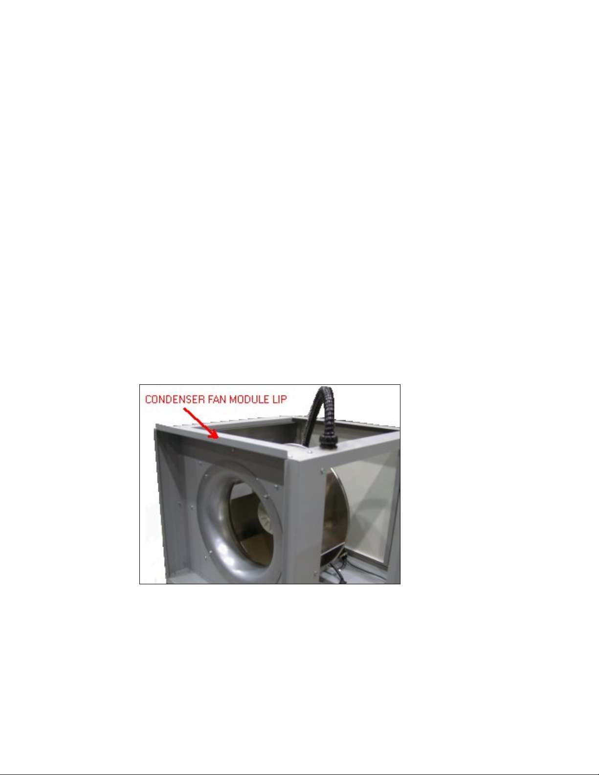
Packaged unit condenser fans
The condenser fan is supplied with a 3’ length conduit/cable assembly. Attach conduit connector through
the 1” hole located at the bulkhead at the top left hand corner of the electrical panel (Figure 3). Connect
the two cables as per wiring diagram to the loom marked condenser fan.
Figure 3
Piping Connections
Condensate Drain
For proper drainage a P-trap MUST be installed. Total height for the trap should be measured from the
bottom of the drain pan (3” above unit bottom), to the bottom of the “U” in the trap. Minimum recommended
height is 3.5” to ensure proper drainage.
Refrigerant Piping
For self contained (packaged) systems no refrigerant connections are required.
Good practice should always be followed when connecting refrigerant piping in direct expansion systems.
As many of the operational problems encountered in a refrigeration system can be traced back to
improper design and installation of refrigerant piping, it is essential that the following guidelines be
observed:
- Use clean and dehydrated refrigeration quality tubing with both ends sealed.
- Cut and form tubes carefully to avoid getting dirt or metal particles into the refrigeration lines. Never
use a hacksaw to cut the tubing.

Series 11 Installation Guide
S11-IM2019 9
- Once the system is open, complete the work as quickly as possible to minimize ingress of moisture
and dirt into the system. Always put caps on ends of tubes and parts not being worked on.
- To prevent scaling and oxidation inside the tubing, pass an inert gas such as nitrogen through the line
while carrying out brazing, silver soldering or any other welding processes.
- It is recommended that quality refrigeration solder (95% tin, 5% silver) is used for its excellent
capillary action.
- Use minimum amount of solder flux to prevent internal contamination of the piping. Use flux with
care as it is usually acidic in nature.
- Install a trap at the bottom of every on the vertical riser of a hot gas or suction line and one for every
6m (20ft.) in elevation to collect refrigerant and lubrication oil during off cycle. A discharge line trap
is an important function both during the compressor on and during the compressor off cycle. During
the on cycle, the trap collects oil droplets and carries them efficiently up the elevated discharge line.
During the off cycle, the traps captures and retains oil residing on the pipe walls that would
otherwise drain back to the compressor head, causing damage on startup.
- Install inverted trap whenever a condenser is located above the compressor. An inverted trap or check
valve should be installed at the condenser inlet and outlet to prevent liquid refrigerant from flowing
backwards into the compressor during off cycles.
- Insulate the suction line and insulate liquid lines that may be subjected to high heat gains. Insulate
low level discharge lines to avoid burning due to accidental contact.
- Design and arrange refrigerant piping for the remote condenser in such a way so that adequate
velocity of refrigerant can be maintained to prevent oil trapping. Under sizing discharge lines will
reduce compressor capacity and increase compressor load. Over sizing discharge lines increases the
initial cost of the project and can reduce the refrigerant gas velocity to a level where oil is not
returned to the compressor.Recommended pipe sizes are tabulated as follows:
Recommended Pipe Size for Remote Condensing Units
Model 1 Ton 1.5 Ton 2 Ton 2.5 Ton 3 Ton 4 Ton 5 Ton
Liquid Line
50 ft. equivalent pipe length 3/8” 3/8” 3/8” 3/8” ½” ½” ½”
Suction Line
50 ft. equivalent pipe length 5/8” 5/8” 3/4” 3/4” 7/8” 7/8” 1 1/8”

Series 11 Installation Guide
S11-IM2019
10
Recommended Pipe Size for Remote Condensers
Model 1 Ton 1.5 Ton 2 Ton 2.5 Ton 3 Ton 4 Ton 5 Ton
Hot Gas Line
50 ft. equivalent pipe length 1/2” 1/2” 5/8” 5/8” 5/8” 3/4” 3/4”
100 ft. equivalent pipe length 1/2” 5/8” 5/8” 3/4” 3/4” 3/4” 7/8”
150 ft. equivalent pipe length 5/8” 5/8” 3/4” 3/4” 3/4” 7/8” 7/8”
175 ft. equivalent pipe length N/A N/A 3/4” 3/4” 7/8” 7/8” 1 1/8”
200 ft. equivalent pipe length N/A N/A N/A 3/4” 7/8” 7/8” 1 1/8”
Liquid Line
50 ft. equivalent pipe length 3/8” 3/8” 3/8” 3/8” 1/2” 1/2” 1/2”
100 ft. equivalent pipe length 3/8” 3/8” 3/8” 1/2” 1/2” 1/2” 1/2”
150 ft. equivalent pipe length 3/8” 3/8” 1/2” 1/2” 1/2” 5/8” 5/8”
175 ft. equivalent pipe length N/A N/A 1/2” 1/2” 1/2” 5/8” 5/8”
200 ft. equivalent pipe length N/A N/A N/A 1/2” 1/2” 5/8” 5/8”
Consult Factory for additional distances
Evacuation
The procedure for leakage testing and evacuation of the system is as follows:
1. Disconnect all line voltage fuses except the fuses for control transformers.
2. Connect a gauge manifold to the compressor suction and discharge access valve.
3. Close the compressor discharge and suction ports and open all service valves.
4. Charge the system with dry nitrogen to approximately 150 psig.
5. Leave pressure in system for at least 12 hours. If pressure holds, continue with next step. If the
pressure drops, detect and seal leak before continuing.
6. Release all pressure. Connect a vacuum pump to the compressor suction and discharge valves with
refrigerant or high vacuum hoses. Provide an isolating valve and a pressure gauge for pressure
checking.
7. Evacuate the system to an absolute pressure not exceeding 1500 microns. Break the vacuum to 2psig
with dry nitrogen. Repeat the evacuation process and then re-break the vacuum with dry nitrogen.
8. Open the compressor discharge and suction ports. Evacuate to an absolute pressure not exceeding
500 microns. Let the vacuum pump run without interruption for minimum two hours.
Ce manuel convient aux modèles suivants
4
Table des matières
Manuels Pompe à chaleur populaires d'autres marques


Mitsubishi Electric
Mitsubishi Electric PUZ-SWM60VAA Manuel utilisateur

Dimplex
Dimplex LI 16I-TUR Guide de l'utilisateur

Carrier
Carrier WSHP Open v3 Guide de configuration rapide

TGM
TGM CTV14CN018A Manuel utilisateur

Carrier
Carrier 38MGQ Series Manuel utilisateur

Kokido
Kokido K2O K880BX/EU Guide de dépannage


