Clearfield FieldShield StrongFiber Manuel utilisateur
FieldShield®StrongFiber Drop Wheel
Installation Manual ______________________________________________________
Manual 019456 REV B - Aug 2018

Direct: 763.476.6866 • National: 800.422.2537 • www.SeeCleareld.com • [email protected]
2
FieldShield®StrongFiber Drop Wheel
Installation Manual _________________________________________________________
Manual 019456 REV B - Aug 2018
Table of Contents
Applications 3
Description 3
Drop Wheel Dimensions 3
Technical Specications 3
Mounting the Drop Wheel Cradle 4
Deploying StrongFiber 5
Assembling Pullable Connector 6
Connector Cleaning Procedure 8
Standard Warranty 11
Proprietary Notice 12
Technical Support 12

3
FieldShield®StrongFiber Drop Wheel
__________________________________________________________ Installation Manual
Direct: 763.476.6866 • National: 800.422.2537 • www.SeeCleareld.com • [email protected]
Manual 019456 REV B - Aug 2018
Applications
• MDU
• FTTH
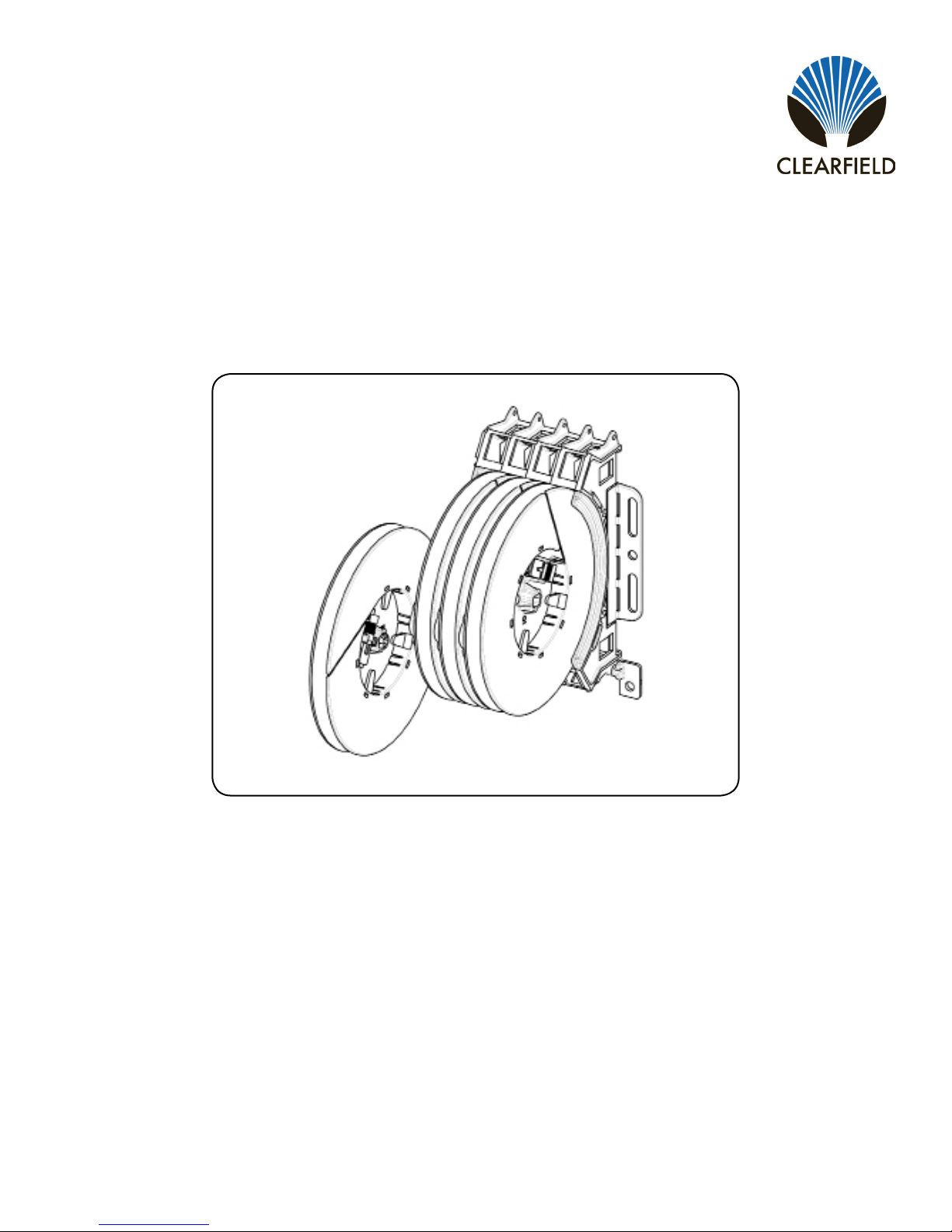
Description
The Drop Wheel provides all the components to distribute drop cables in
a compact, quick deploy platform. Each Drop Wheel is spooled with 200
feet of FieldShield Strong Fiber pre-terminated with a pullable SC/APC
or SC/UPC and a matching standard connector. Once mounted, Drop
Wheels can be easily deploy be extending the wheel from the cradle,
pulling the ber through the microduct, and then assembling the pulled
connector. Drop Wheel assemblies can be ordered in 4, 8, 12 and 16
ports.
Drop Wheel Dimensions
5.09”
5.30”
8.19”
Technical Specications
Characteristic Specication
Material Black Thermoplastic
Fiber 200 Feet of FieldShield Strong Fiber
Connectors Pullable SC/APC to Standard SC/APC (SC/UPC available)

Direct: 763.476.6866 • National: 800.422.2537 • www.SeeCleareld.com • [email protected]
4
FieldShield®StrongFiber Drop Wheel
Installation Manual _________________________________________________________
Manual 019456 REV B - Aug 2018
Mounting the Drop Wheel Cradle
Secure the drop wheel cradle with the provided screws following the provided hole diagram.
NOTE: In earthquake regions,the drop wheel cradle requires three screws per side.

5
FieldShield®StrongFiber Drop Wheel
__________________________________________________________ Installation Manual
Direct: 763.476.6866 • National: 800.422.2537 • www.SeeCleareld.com • [email protected]
Manual 019456 REV B - Aug 2018
1. Mount Drop Wheel cradle into appropriate mounting holes (previous page),
mounting the block of Drop Wheels with the ber termination ports oriented at
the top of the Drop Wheel cradle as shown in (Figure 1).
Note: Fiber peels off to the back of the wheel.
2. Pull/extend desired wheel forward (Figure 1), carefully remove tape holding
the ber in place (Figure 2).
3. Loop a half hitch knot around the connector at the rst notch in the crimp tube,
tie the microduct pull string to the connector pulling eye (Figure 3).
4. Feed the connector into the microduct, and with the drop wheel extended,
carefully pull the ber through the microduct (Figure 4).
Figure 1
Figure 2 Figure 3 Figure 4
Deploying StrongFiber

Direct: 763.476.6866 • National: 800.422.2537 • www.SeeCleareld.com • [email protected]
6
FieldShield®StrongFiber Drop Wheel
Installation Manual _________________________________________________________
Manual 019456 REV B - Aug 2018
Step 1: Remove the white protective dust cap from the
unassembled connector (Figure 1).
Note: The SC Pushable Connector has a keyed locking
feature that holds the inner housing to the connector and
aligns the ferrule when the two are correctly mated.
To properly mate the connector, the key on the inner housing
must bypass the ferrule alignment notch to properly lock into
place.
Figure 1
Step 3: Rotate counter-clockwise 45 degrees to realign the
inner housing and connector and push the inner housing onto
the connector until it snaps into place (Figure 3).
Step 2: Align the black mark on the inner housing with the
black line on the connector, then rotate the inner housing
45 degrees to offset the lock (Figure 2) and slide the inner
housing half way over the connector.
Figure 2
Figure 3
Figure 4
Figure 5
Step 5: Re-install the white protective dust cap (Figure 5).
Step 4: Align the key on the outer housing with the black line
on the connector, then slide the outer housing over the entire
assembly until it snaps into place (Figure 4).
5. Assemble the connector, following instructions on the package or the steps below:
Assembling Pullable Connector

7
FieldShield®StrongFiber Drop Wheel
__________________________________________________________ Installation Manual
Direct: 763.476.6866 • National: 800.422.2537 • www.SeeCleareld.com • [email protected]
Manual 019456 REV B - Aug 2018
6. At the Drop Wheel, route the standard
connector from the center of the Drop Wheel
through the access slot on the side of the Drop
Wheel to the appropriate port on the Drop
Wheel Cradle (Figure 5).
Note: Additional slack can be stored in the
connector access slot in the middle of the drop
wheel
7. Reinsert the Drop Wheel into the mounting
bracket. Make sure that the slide is properly
aligned when reinserting the drop wheel
(Figure 6).
Figure 5
Additional Slack
Storage
Figure 6
Note: Incorrect Position

Direct: 763.476.6866 • National: 800.422.2537 • www.SeeCleareld.com • [email protected]
8
FieldShield®StrongFiber Drop Wheel
Installation Manual _________________________________________________________
Manual 019456 REV B - Aug 2018
Whether factory terminated or eld spliced, clean connectors are essential
for proper system operation. Even the smallest dust particle can cause
transmission problems, so for optimal network performance, inspect and if
necessary, clean all connectors and adapters prior to mating.
I.T.C…Inspect Then Connect!
ALWAYS inspect the connector rst thing with a clean ber scope inspect
the pair. Three types of contamination require different cleaning techniques.
The use of Chemtronics end face and bulkhead cleaning products and
techniques ensures a clean end face, no matter the type of contamination.
These are Cleareld recommended products/application. Use the product
you feel will complete your cleaning procedures. Create a “best practice” for
your company and follow those procedures.
**Note: It is NOT recommended to use IPA to clean the end-face.
Cleaning the end-face…but not just the end-face
• Place one wiping paper on QbE-2 FiberSafe™ Cleaning Platen. Figure 1
• Apply small amount of precision cleaner (about 1” in diameter) with Elec-
tro-Wash MX pen on to one end of the wipe. Figure 2
• Hold end face 90 degree. Adjust for APC connection by slightly tilting the
container or end face. Angle is correct when no drag is left on the end face.
Figure 3
• Draw end face from wet to dry part of the wipe 3 times. Use just enough
pressure to ensure complete contact between end face and the wipe.
DO NOT retrace previous step.
Figure 1
Figure 2
Figure 3
Connector Cleaning Procedure

9
FieldShield®StrongFiber Drop Wheel
__________________________________________________________ Installation Manual
Direct: 763.476.6866 • National: 800.422.2537 • www.SeeCleareld.com • [email protected]
Manual 019456 REV B - Aug 2018
• CLEAN THE FERRULE…Lightly moisten the ber optic swab
(2.5mm/38542F or 1.25mm/38040) by spotting a small amount (about 1”)
of Electro-Wash PX or Electro-Wash MX pen onto the QBE-2. Hold the
swab, 1 side down to the wetted area and hold for a count of 1-2-3-4-5.
Figure 4
• Insert swab into side of ferrule, wet side to the ceramic ferrule and
circle around 2-3 times and remove. Turn swab to dry side and repeat.
Figure 5
Cleaning the mate through a bulkhead adapter AND the
adapter itself!
• Lightly moisten the ber optic swab(2.5mm/38542F or 1.25mm/38040)
by spotting a small amount (about 1”) of Electro-Wash PX or Elec-
tro-Wash MX pen onto the QBE-2. Hold the tip of the swab onto the
wetted area and hold for a count of 1-2-3-4-5.
• Insert the swab into the adapter to the connector, press lightly against
the connector, twist 2-3 times, remove and discard.
• Dry with a second dry swab.
• Inspect (re-clean if necessary) and test for signal strength.
• Use additional swabs to clean inside the actual adapter. Moisten swab,
like above, insert through hole and remove while twisting. Figure 6
Figure 4
Figure 5
Figure 6

Direct: 763.476.6866 • National: 800.422.2537 • www.SeeCleareld.com • [email protected]
10
FieldShield®StrongFiber Drop Wheel
Installation Manual _________________________________________________________
Manual 019456 REV B - Aug 2018
Cleaning an MPO/MTP Connector
Female Connector
• Place one wiping paper on QbE-2 FiberSafe™ Cleaning Platen and
apply small amount of precision cleaner (about 1” in diameter) with Elec-
tro-Wash MX pen on to one end of the wipe. Figure 1
• Hold end face 90 degree. Adjust for APC connection by slightly tilting
the container or end face. Angle is correct when no drag is left on the end
face. Figure 2
Male Connector
• Lightly moisten the ber optic swab (CC505F) like above, moistening 1
side.
• Place swab, wet side down at one end of connector end-face and draw
across in a diagonal sweep (ie: from ber 1 up and across to ber 12).
Turn swab over to dry and draw back from ber 12 to ber 1. Figure 3
BEFORE cleaning any connector…be sure you know what type of con-
taminate you are cleaning…dry? Fluidic?...All the available products are
good, it’s the process that you need to be aware of. Using a dry cleaning
method to clean “dirt” can lead to scratching of the end-face. Learn the
process of cleaning properly!
Figure 1
Figure 2
Figure 3
Table des matières
Autres manuels Clearfield Accessoires réseau


Manuels Accessoires réseau populaires d'autres marques


Patton electronics
Patton electronics 2888 Manuel utilisateur

Cradlepoint
Cradlepoint COR IBR1100/IBR1150 Manuel utilisateur

Paradyne
Paradyne Hotwire 8620 Manuel utilisateur

Infra Cool
Infra Cool F-1.3 Manuel utilisateur

Edgewater Networks
Edgewater Networks 4300T Manuel utilisateur

Edimax
Edimax SB-2200g Manuel utilisateur

Extreme Networks
Extreme Networks Mogul-100 Manuel utilisateur

Aaeon
Aaeon FWS-8500 Manuel utilisateur

Panduit
Panduit Z11C Series Manuel utilisateur

F5
F5 BIG-IP 10000 Series Instructions de montage

ZyXEL Communications
ZyXEL Communications NMA1115 Manuel utilisateur

Auerswald
Auerswald COMtrexx Business Manuel utilisateur