Claro GLIDER DC Manuel utilisateur

GLIDER DC
Installation Manual
VER 0.1

1
CEILING FAN INSTRUCTION BOOKLET
Thank you for purchasing your Claro Glider DC Ceiling Fan.
Please read all instructions carefully before assembly and use.
IMPORTANT SAFEGUARDS:
Read all instructions carefully, even if you feel you are quite familiar with this type of appliance. When
using electrical appliances, in order to reduce the risk of fire, electric shock, and/or injury, these
basic safety precautions should always be followed:
1. All wiring must be done by a licenced electrician as on-site warranty may be voided if proof cannot
be provided. This ceiling fan MUST be installed by a Qualified Electrical Contractor in accordance
with the local regulations, and all local, state and national electrical codes. Any alterations or
additions to building wiring must be completed by a licensed electrical contractor, or person
authorised by legislation to work on the fixed wiring of any electrical installation.
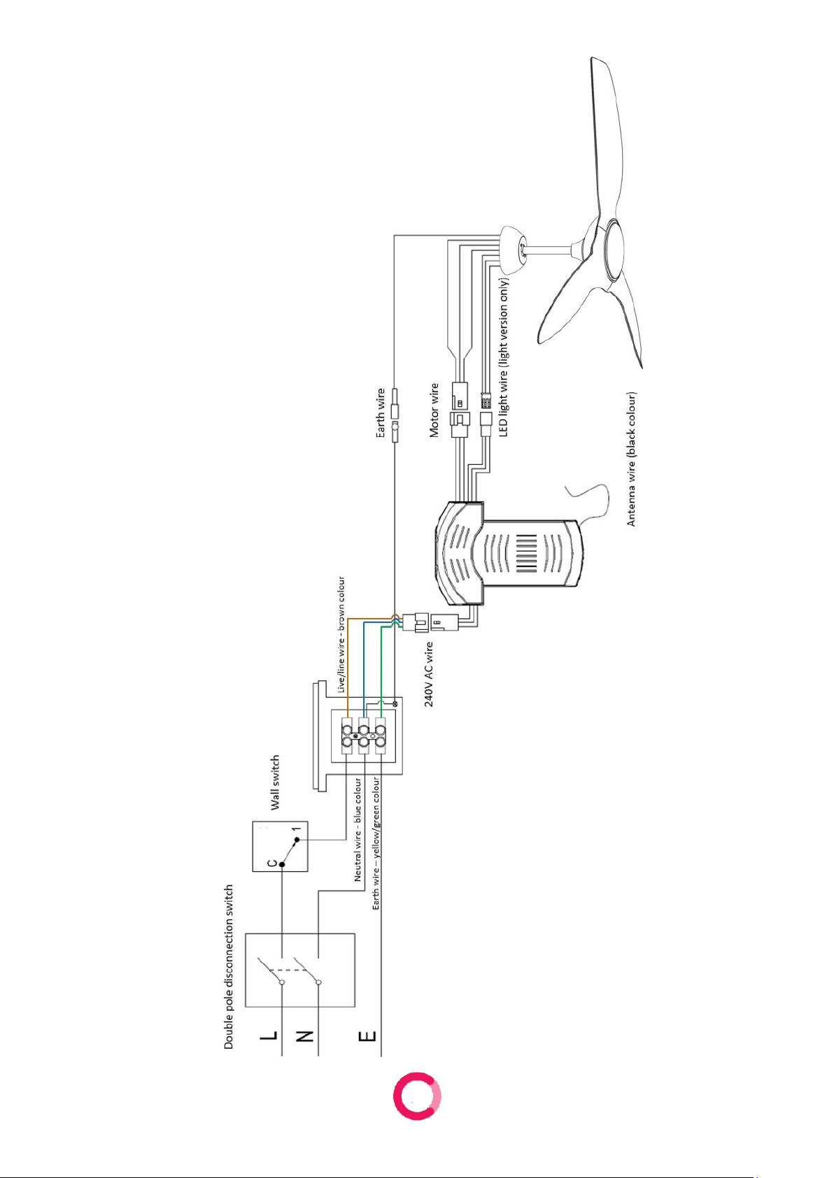
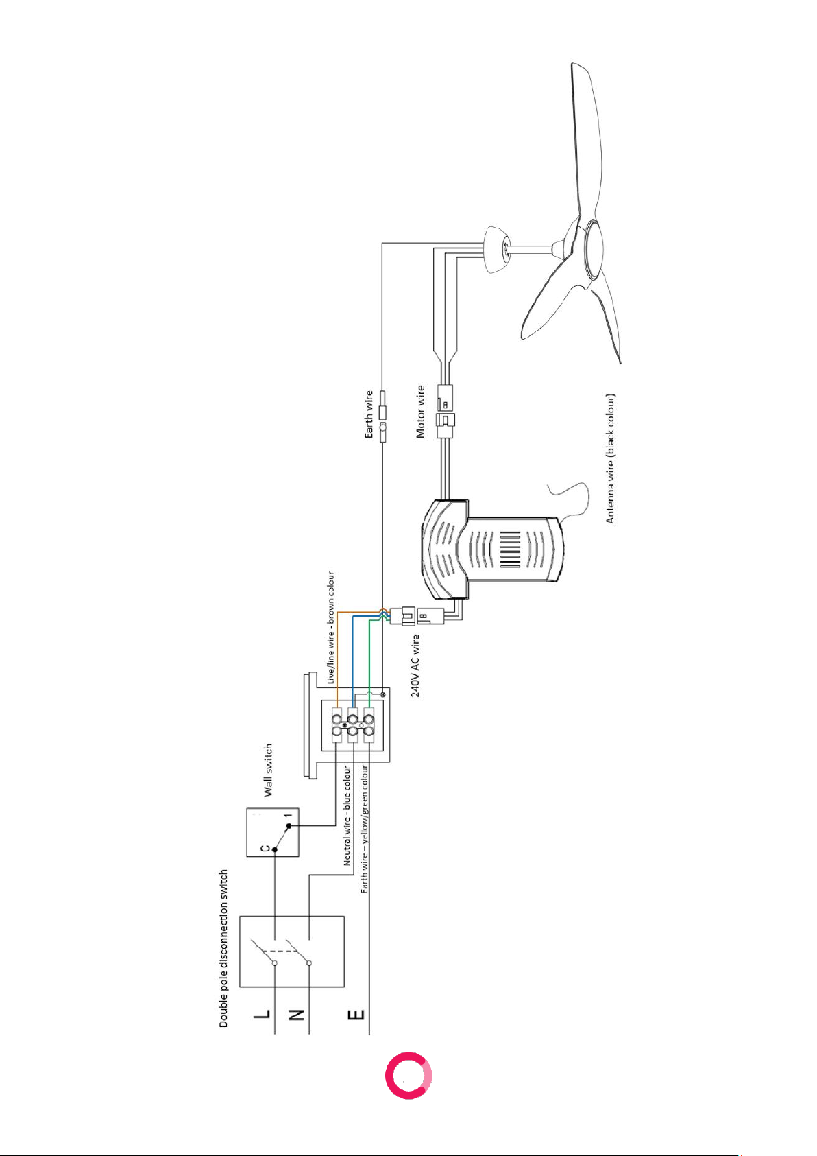
2. The fan must be connected to a 240V AC 50Hz power supply.
3. All electrical work must only be undertaken after disconnection of the power by removing fuses or
turning off the circuit breaker, to ensure all pole isolation of the electrical supply.
4. The fan must be earthed.
5. The fan must be installed so that the blades are at least 2.1 metres above the floor.
6. The ceiling fan weight is max.7.0kg. The structure that the ceiling fan is mounted to must be
capable of supporting a weight of at least 45kg. The fixing must be able to support the moving
weight of the fan and must not twist or work loose.
7. Make sure that the installation site will not allow the rotating fan blades to come into contact with
any object and that there is enough space from the blade tip to the wall or ceiling. Please note that
insufficient clearance distances might cause wobbling and the bigger this clearance is the better the
airflow from your fan will be.
8. This product can be installed in a position where it is covered or enclosed alfresco areas and there
is a minimum clearance of 1.50 m from the blade tip to all edges of the roof or positions where it
could be exposed to water, moisture or other dangerous external elements.
9. DO NOT connect the fan motor to a dimmer switch. This may give an unsatisfactory performance
(motor hum) and cause damage to the motor and/or controller. Use ONLY the provided remote
control.
10. This appliance is not intended for use by young children or infirm persons without supervision.
Young children should be supervised to ensure that they DO NOT play with the appliance.
11. It is NOT recommended that ceiling fans and gas appliances be operated in the same room at the
same time.
12. The fan must be turned off and stopped completely before reversing the fan direction. This will
prevent any damage to the motor of the fan or controller.
13. Do not insert anything into the fan blades whilst they are spinning. This will damage the blades and
upset the balance of the fan causing the unit to wobble.
14. After the fan is completely installed make sure that all base and fan blade fixings are secured and
tightened to prevent any problems.
15. Because of the fan’s natural movement, some connections may loosen. Check the support
connections, brackets and blade attachments twice a year to make sure they remain secured. If any
are loose, tighten.
16. If unusual oscillating movement is observed, immediately stop using the ceiling fan and contact the
manufacturer, its service agent or suitably qualified persons.

2
17. The replacement of parts of the safety suspension system device shall be performed by the
manufacturer, its service agent or suitably qualified persons.
18. If it is necessary to replace the live or neutral brushes to ensure operation of the motor then
both brushes and the earth brush shall be replaced at the same time. The brushes shall only be
replaced by a suitably qualified person.
19. An all-pole disconnection incorporated in the fixed wiring is to be provided, such as an all-pole
switch or a supply cord fitted with a plug.
20. The remote/receiver included is intended to be used with this fan and associated light component
ONLY and is not compatible with any other lighting and/or any other electrical device. Use of it in
any way other than intended may result in damage to the fan, receiver and/or other devices and as
such, will void warranty.
21. The LED light panel in light kit is user replaceable as it connects with 'Push Plug' wiring. It is user
replaceable ONLY with Claro certified replacement LED panels. Using unauthorised parts may
damage the fan, cause undesired results, or be a safety hazard.
22. The max operating temperature for the fan is 40°C. Keep the fan away from any heat sources, like
fire place, heater and stove.
23. Reasonable ‘wear and tear’ is not covered under warranty. For comprehensive warranty terms &
conditions visit clarofans.com.au
IMPORTANT NOTE:
The important safeguards and instructions given in this manual are not meant to cover all possible
conditions and situations that may occur. It must be understood that common sense, caution and care
are factors which cannot be built into any product.
CAUTION:
•DO NOT ingest battery - Chemical burn hazard
•The remote supplied with this product contains 2xAAA batteries. If the battery is swallowed, it can
cause severe internal burns in just 2 hours and can lead to death
•Keep the new and used batteries away from children. Examine devices regularly, and ensure the
battery compartment is secure
-If the battery compartment does not close securely, stop using the product and keep it away
from children
•If you think the batteries might have been swallowed or placed inside any part of the body, seek
immediate medical attention
-Call the Poisons Information Centre on 13 11 26 or go to a hospital emergency room
-DO NOT let the child eat or drink or induce vomiting. Dispose of used button batteries
immediately
•The batteries supplied with this product is not to be recharged
•Different types or new and used batteries are not to be mixed
•Battery to be inserted with the correct polarity; ‘+’for positive, ‘-’for negative
•Exhausted batteries are to be removed from the appliance and safely disposed of
•If the appliance is to be stored unused for a long period, the batteries should be removed
•Dispose of used button batteries immediately
•Flat batteries can still be dangerous
•The supply terminals are not to be short-circuited

3
FAULT FINDER:
Always check the “Trouble Shooting Checklist” included in this manual before seeking a warranty
claim.
A mechanical noise may be noticed on installation. Allow at least 8 hours settling-in period.
Some fans may wobble more than others, even if they are identical. This does not necessarily
indicate a fault.
PREPARATION:
1. Unpack your ceiling fan carefully, then remove all parts and components, and lay on a cloth or soft
surface to avoid damage.
DO NOT lay the motor housing on its side as the housing may get damaged.
2. Before commencing installation, check that all parts are included.
NOTE: You may need to remove all foam packaging material to ensure there are no missing parts.
List of Components
1. Hanging Bracket
2. Ball Joint
3. Downrod
4. Canopy
5. Coupler Cover
6. Motor
7. Blades
8. Blade Screws
9. LED Light (light version)
10. Light Screws (light version)
11. Diffuser (light Version)
12. Bottom Plate (no light version)
13. Screw Pack and Balancing Kit
14. Receiver and Remote Pack

4
INSTALLATION AND ASSEMBLY:
CAUTION! Before installing the fan make sure you have turned OFF the electricity supply.
SELECTING A LOCATION:
1. Choose a location for mounting the fan where the blades will have at least 2.1 metres of clearance
from the floor.
2. Make sure that the installation site will not allow the rotating fan blades to come into contact with
any object and that there is enough space from the blade tip to the wall or ceiling. Please note that
insufficient clearance distances might cause wobbling and the bigger this clearance is the better the
airflow from your fan will be.
3. If the location you have chosen does not have a suitable support beam capable of supporting 45kg,
install a brace 2” x 4” between the ceiling joists as a support medium.
4. Secure the hanging bracket to the ceiling joist or suitable structure that is capable of carrying a load
of at least 45kg, with the two long fixing screws provided. Ensure that at least 30mm of the screw is
threaded into the support.
NOTE: The fixing screws included are designed for use when ceiling fan is secured onto timber
joists. For all other surfaces, additional and suitable fixing screws for that surface will need to be
purchased.
5. This product can be installed in a position where it is covered or enclosed alfresco areas and there
is a minimum clearance of 1.50 m from the blade tip to all edges of the roof or positions where
could be exposed to water, moisture or other dangerous external elements.
6. Wear and tear, including exposure from the elements, is not covered under warranty.
7. This product is not approved for coastal use or other locations with high salt content in the air (e.g.,
near a salt water pool) and includes installation indoors. Any motor or mechanical fault caused by
the salt, will not be covered under warranty.
NOTE:A location is considered a coastal area anywhere up to about 20km from the ocean (or
similar), and the air has a high salt content. Due to different geographical locations, the exact
distance and location that may be considered coastal may vary.

5
WIRING DIAGRAM
LIGHT MODEL

6
NO LIGHT MODEL

7
ELECTRICAL CONNECTIONS:
Ensure the power is OFF when installing this fan.
INSTALLATION STEPS:
1. Secure the hanging bracket to the ceiling joist or suitable structure that is capable of carrying a load
of at least 45kg.
CAUTUION: Ensure building cable is able enter the canopy close to terminal block.
2. Remove cotter-pin and cross-pin from downrod and loose two set screws and ball pin from hanging
ball. Ensure all pieces are carefully put aside.
3. Take the and keep the side with 3 holes up.
Ball Pin
Set Screw
Earth
Wire
Cross-pin
Cotter-pin

8
4. Feed the main motor and light wire (light version only) plug up through the inside of the down rod,
then insert the down rod into the downrod holder. Gently push the cross-pin through the holes
aligned with the base of the downrod holder and downrod. Insert cotter pin into cross pin and
secure downrod with two set screws.
CAUTION: DO NOT force the cross-pin. Gently wiggle and rotate it until it glides through both
holes. The rod installs with the 3 holes up.
5. Snuggle the coupling cover down onto the top of the motor housing. Put the canopy through the
downrod.
CAUTION: DO NOT remove rubber gasket on top of the coupling cover.
Set Screw
Cross-pin
Cotter-pin

9
6. Place the hanging ball on top of the downrod
7. Secure it with the ball pin and two set screws.
8. Tighten one fan blade with 3 screws from under the motor.
9. Repeat with the remaining 2 fan blades.
10. Hang the fan into hanging bracket. Align ball groove on hanging ball with ridge on hanging bracket.
Ensure hanging ball sitting into hanging bracket correctly. If fan doesn’t sit properly, hold the
downrod and twist it until fan has been secured into hanging bracket.
Ball Pin
Set Screw
Earth
Ball Groove
Ridge
Table des matières
Autres manuels Claro Ventilateur


