Cisbo Parking sensor Manuel utilisateur

Parking sensor
CISBO
CISBO RADER SYSTEM USER’S MANUAL

Index
!TO USER --------------------------------------------------------------1
!PARTAND TECH DATA---------------------------------------------2
!DISPLAY ANDALARM SOUND-----------------------------------3
!INSTALLATION FOR 2&4 SENSORS-----------------------------4
!INSTALLATION FOR 6&8 SENSORS-----------------------------5
!INSTALLATION FOR WIRELESSTYPE--------------------------6
!INSTALLATION FOR VIDEOTYPE-------------------------------7
!INSTALLATION FOR REARVIEWMIRROR TYPE-------------8
!POSITION FOR EACH PART------------------------- --------------9
!DISPLAY &MAIN BOX INSTALLATION DIAGRAM----------10
!SENSORS INSTALLATION DIAGRAM--------------------------11
!NOTICE FOR USER-------------------------------------------------12
!FUNCTIONS FOR LED DISPLAY SERIES-----------------------13
!FUNCTIONS FOR LCD DISPLAY SERIES-----------------------14
!FUNCTIONS FOR REARVIEWMIRROR SERIES---- ----------15
!FUNCTIONS FOR VIDEO DISPLAY SERIES--------------------16
!GUARANTEE FORM -----------------------------------------------17

TO USER
Thank you for choosing and using our Parking Sensor products. We
are going to provide you with the best products and the best services. In
order to insure the best performance and avoid any false alarm or
function failure, we strongly suggest that you read this user's manual
carefully before installation and use.
Parking Sensor System is a high technology product. It adopts
ultrasonic wave sensors to measure the distance between your car and
the obstacles, and remind the driver of safe distance accurately when
reversing a car.
We reserve all rights for our Parking Sensor products, including the
designs and the software. Any unauthorized copy or translation is
prohibited. And the content of the user's manual will be updated
according to the update of the products, if it is subjected to change,
without notification. At last, the final explanation rights of this user's
manual is reserved by us.
CISBO RADER SYSTEM USER’S MANUAL

2
PART
1.
2.
3.
4.Camera: input thevideo signal, normallybe set inthe rear bumper.
5.
Display: Back visiondisplay, distance numeric display, buzzer alarmcircuit , etc,
normally set insidethe driving room.
Control unit: MCU control circuit, normally set inside the trunk, nearby the
backup lights.
Sensor: .Ultrasonic sensor "electronic eye", is the transmisson center for detecting
signals and normallyset at therear or frontof bumper.
Mobile phone handsfree system: Beset inside therear view mirror, connected with
the mobile, bringconvenience and safetyduring circumstance.
TECH DATA
1.
2.
3.
4.
5.
6. Radio frequency: 315MHz/433MHz
7. Camera angle: 92 or 120
Rated voltage : DC12V (24v available)
Power : 3.6W
Workingtemperature: -20 C---70 C
Detecting distance: 0.3-2.0M
Detecting angle: H>60 ,V>60
CISBO RADER SYSTEM USER’S MANUAL
3
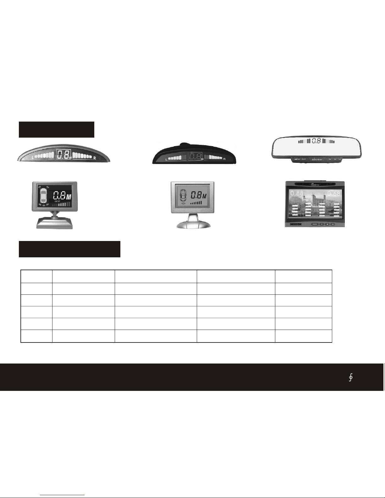
DISPLAY
LED DISPLAY
LED DISPLAY WITH HANDFREE
LCD DISPLAY LCD DISPLAY TFT LCD MONITOR
ALARM SOUND
safe mode
safe mode
alarm mode
alarm mode
danger mode
1
2
3
4
5
200-160cm
150-100cm
90-50cm
40-30cm
0-20cm
NO
Bi----Bi----Bi
Bi--Bi--Bi
Bi-Bi-Bi
Bi------------
2.0-1.6
1.5-1.0
0.9-0.5
0.4-0.3
0.0
Stage
Distance
Awareness
Display
Alarm
CISBO RADER SYSTEM USER’S MANUAL
LED DISPLAY

INSTALLATION FOR 2 & 4 SENSORS
1. This diagram only for 2 and
4 back sensors.
2. The system begin to work
while the car on reversing
time.
3. The display such asLED
display, LCD display, only
Buzzer, rearview mirror,
detail see Page 3.
4. The sensors will be on
flashing while the car on
brake time if the system be
Matched the illuminant sensor..
5.Power line guide:
Reversing light: Power on
while the car on reversing
time.
Stop light: poweron while
brake.
SENSOR A
SENSOR B
SENSOR C
SENSOR D
4 SENSORS
2 SENSORS
BLACK GND
Reversing
light
RED +12v
DISPLAY
MAIN BOX
INSTALL ON THE BACK BUMPER
YELLOW 12v
Stop
light
(Only for lliuminant sensor)
CISBO RADER SYSTEM USER’S MANUAL

INSTALLATION FOR 6 & 8 SENSORS
1. This diagram only for 6 and
8 sensors(Front and back).
2. The front sensors begin to
work while the car onbrake
Time.
3. The back sensors begin
work while the car on
Reversing time.
4. The display such as LED
display, LCD display, only
Buzzer, rear view mirror,
detail see Page3.
5.Power line guide:
Reversing light: Power on
while the car on reversing
time.
Stop light: power on while
brake.
MAIN BOX
BLACK GND
RED +12v
YELLOW 12v
Reversing
light
Stop
light
DISPLAY INSTALL ON THE BACK BUMPER
4 SENSORS
SENSOR A
SENSOR B
SENSOR C
SENSOR D
SENSOR E
SENSOR F
SENSOR G
SENSOR H
INSTALL ON THE FRONT BUMPER
CISBO RADER SYSTEM USER’S MANUAL

INSTALLATION FOR WIRELESS TYPE
1. This diagram only for
wireless parking sensor.
2. The back sensors begin to
work while the car on
reversing time.
3.the sensors will be on
flashing while the car on
brake time if the system be
matched the illuminant
Sensor.
4. The display such as LED
display, LCD display, only
Buzzer, rear view mirror,
detail see Page 3.
5.Power line guide:
Reversing light: Power on
while the car on reversing
time.
Stop light: power on while
brake.
BLACK GND
RED +12v
YELLOW 12v
Reversing
light
Stop
light
(Only for lliuminant sensor)
4 SENSORS
2 SENSORS
MAIN BOX DISPLAY
SENSOR A
SENSOR B
SENSOR C
SENSOR D
INSTALL ON THE BACK BUMPER
TO CIGARETTE JACK +12V
BLACK GND
RED +12v
YELLOW 12v
CISBO RADER SYSTEM USER’S MANUAL

INSTALLATION FOR VIDEO TYPE
1. This diagram only for the
parking sensor with camera.
2. When the car on reversing ,
the back sensors and
camera are working.
3.The imagine will display on
the external TFT screen,
while the distance will
display as well.
4. The display is used for car
DVD/VCD.
5.Power line guide:
Reversing light: Power on
while the car on reversing
time.
Stop light: power on while
brake.
BLACK GND
RED +12v
Reversing
light
Camera
TO CAMERA
TO CAMERA
TFT Screen (optional)
DC PLUG
YELLOW VIDEO
WHITE BUZZER
BUZZER
SENSOR A
SENSOR B
SENSOR C
SENSOR D
4 SENSORS
2 SENSORS
INSTALL ON THE BACK BUMPER
INSTALL ON THE BACK BUMPER
CISBO RADER SYSTEM USER’S MANUAL

INSTALLATION FOR REARVIEW MIRROR TYPE
1. This diagram only for 4 in 1
or 6 in 1 parking sensor
2. The back sensors begin to
work while the car on
reversing time.
3.the sensors will be on
flashing while the car on
brake time if the system be
matched the illuminant
sensor.
4. The function see detail
Page 15.
5. The display clip on the
original rearview mirror.
6.Power line guide:
Reversing light: Power on
while the car on reversing
Time.
Stop light: power on while
brake.
YELLOW 12v
Reversing
light
(Only for lliuminant sensor)
INSTALL ON THE
BACK BUMPER
BLACK GND
MAIN BOX
RED +12v
Stop
light
DISPLAY
4 SENSORS
2 SENSORS
TO CIGARETTE JACK +12V
SENSOR A
SENSOR D
SENSOR C
SENSOR B
MOBILE PHONE
CISBO RADER SYSTEM USER’S MANUAL
Table des matières


