Cirs 069A Manuel utilisateur

USER GUIDE
900 Asbury Ave • Norfolk, Virginia 23513 • USA • Tel: 757-855-2765 • WWW.CIRSINC.COM
Model 069A


Table of Contents
Overview
................................................................................................................................................................3
Instructions for Use
.................................................................................................................................................4
Handling and Care
...............................................................................................................................................4
Testing Procedures
.................................................................................................................................................7
Sensitivity (Depth of Penetration) .....................................................................................................................7
Velocity Accuracy .............................................................................................................................................9
Angle Error Test
..................................................................................................................................................9
Specifications
...................................................................................................................................................... 10
ZERDINE® ........................................................................................................................................................ 11
Appendix 1: Conversion of Flow
Rate to Flow Velocity
.................................................................................................. 13
Warranty
............................................................................................................................................................. 12

Overview
The Doppler Ultrasound Flow Phantom is a tissue mimicking phantom that may be used with a Pump and
Doppler Fluid to perform quality assurance testing of Doppler ultrasound devices.
When use in conjunction with the CIRS Doppler Flow Pump (Model 769) it will mimic the acoustic properties
of blood flow and may be used to perform quality assurance testing of Doppler ultrasound devices in compliance
with IEC61685.
The three most common tests: sensitivity, velocity accuracy measurements, and angle error are described in this
manual, while the References section provides sources for additional information about Doppler Ultrasound
Performance Testing.
Description of the Phantom
Flow phantom contains a blood-vessel-simulating, ultrasound-compatible tube. The phantom has both a top and
bottom scanning surface (see Figure 1) that allows testing at varying depths and angles of orientation. This
makes the phantom suitable for testing both peripheral flow and deeper abdominal vessels. The phantom is filled
with Zerdine® tissue mimicking gel with a speed of sound of 1540 m/s, an attenuation of 0.7 dB/cm/MHz and a
backscatter contrast designed to match that of the liver. It is housed in rugged ABS plastic for added durability.
Instructions for Use
Follow the proper set up procedure included in the Model 769 User Guide.
SPECIFICATIONS
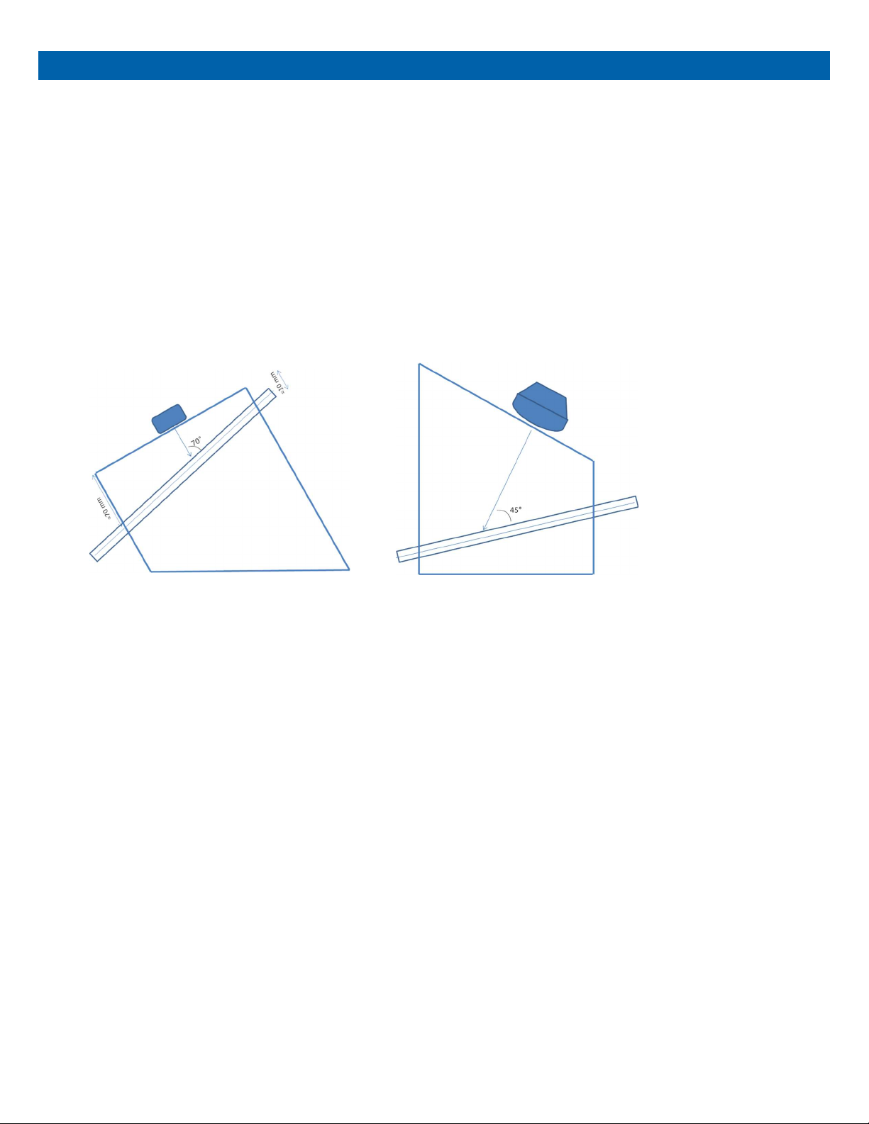
The phantom has two scanning surfaces that are designed to allow testing at shallow depths and vessel
angles commonly encountered in peripheral vascular imaging, as well as deeper vessels more common in
abdominal applications. The simulated blood vessel embedded within the phantom is made of ultrasound-
compatible C-flex® tubing with an inside dimension of 3/16” and an outside dimension of ¼”. Figure 1
illustrates the two imaging configurations for the phantom.
Figure 1 Phantom used for peripheral Doppler imaging (left) and for abdominal applications (right).
The simulated vessel is embedded in tissue equivalent Zerdine® gel with the following acoustic properties:
Speed of sound: 1540 m/s
Attenuation coefficient: 0.7 dB/cm/MHz
Relative backscatter: 0 dB with respect to CIRS liver parenchyma reference
HANDLING PRECAUTIONS AND END OF LIFE DISPOSAL
With proper care, the tissue mimicking phantom enclosed with the Doppler Flow Simulator will withstand
years of normal use. Below are some guidelines to follow:
The scanning surface is the most important item on the phantom to protect. It can withstand normal scanning
pressure but DO NOT press on the scanning surface with your fingernails or any other sharp objects. If the
scanning surface becomes damaged, seal the phantom in an airtight container and IMMEDIATELY contact
CIRS for return authorization. Call 800-617-1177, email at rma@cirsinc.com or fax RMA Request form to 757-
857-0523.
The phantom may be cleaned with mild soap and water ONLY. Avoid solvent-based, alcohol-based, or
abrasive cleaning agents.

For longest life, the phantom should be stored at room temperature. The phantom SHOULD NOT be
subjected to freezing or boiling conditions such as those encountered in the trunk of a car during a South
Dakota winter or Arizona summer. The most accurate measurements will be made with the phantom 22˚C ±
1˚C (70˚F – 73˚F).
Always store the phantom with the removable storage cover attached and in the airtight carry case provided
to maximize life expectancy.
Zerdine® will desiccate over time if the phantom is not stored properly. If there is a noticeable change in the
phantom the phantom should be returned IMMEDIATELY for repair or replacement.
Inspect your phantom regularly for signs of damage.
Regular inspection for weight loss is essential to maintaining your phantom. At least once a
year, weigh your phantom and com- pare to original weight noted on certificate of compliance.
If phantom has lost or gained more than 1% of its original weight and you notice a difference in
vertical distance measurements, or the scan surface appears depressed, call CIRS at (800)
617-1177.
This product contains Zerdine, a non-flowing water-based, polyacrylamide material which is
fully sealed within the phantom housing. Zerdine contains trace amounts of residual monomer
acrylamide CAS#79-06-1. There are no known hazards when the phantom is used and stored
as intended. Zerdine is fully cured and will not leak from the housing. Damage to the integrity of
the housing may expose the user to Zerdine containing trace monomer acrylamide below levels
necessary to cause adverse health effects. Nonetheless, it is advised to wear protective gloves
if handling exposed Zerdine gel. It is also advisable to wash hands and all surfaces with soap
and water after handling exposed Zerdine gel.
Regulations regarding disposal of materials with trace acrylamide monomer vary by locality.
Contact your local authority for instructions. If assistance is desired in the proper disposal of
this product, including accessories and components, after its useful life, please return to CIRS.

Handling and Care
The phantom may be stored with the rest of the flow circuit connected, so long as the pump is used often. If
you do not anticipate further testing for several weeks, we recommend purging the circuit of blood mimicking
fluid to prevent particle agglomeration. To do so, follow the steps below:
1
.
Disconnect the reservoir outlet from the pump and leave the tube in the air.
2
.
Run the pump pumping until all remaining fluid is returned to the reservoir.
3
.
Turn off the pump, disconnect the reservoir cap and place it over a container of water. Turn the pump back
on and clean any remaining blood mimicking fluid from the circuit. When complete, turn off the pump. DO NOT
DRAIN THE REMAINING WATER FROM THE TUBES IN THE PHANTOM
.
This will prevent the tubing from
collapsing and extend the phantom lifetime.
4. Store the Doppler Flow Pump in accordance with the Model 769 User Manual.

TESTING PROCEDURES
Below is a description of the three most common Doppler ultrasound performance tests that may be
conducted with this phantom: sensitivity, velocity accuracy and angle error. Additional Doppler performance
tests of interest are described in detail in the following references.
1
.
Performance Criteria and Measurements for Doppler Ultrasound Devices: Technical Discussion; Second
Edition. AIUM Technical Standards Committee, 2002.
2
.
Testing of Doppler Ultrasound Equipment. Institute of Physical Sciences in Medicine, Report No. 79, ed.
PR Hoskins, SB Sherriff and JA Evans, 1994.
3
.
IEC TS 61895: Ultrasonics – Pulsed Doppler diagnostic systems – Test procedures to determine
performance. First edition, 1999-10.
For sensitivity, velocity accuracy and angle error tests described below, there will be considerable variability
based on the system settings and operator technique. In addition, there may be some measurement bias
between the pump settings and the velocity measurement. There- fore, it is recommended that when using
this phantom as part of a QA program, the user should conduct a series of baseline measurements to
establish the measurement error bars. These error bars are essential for establishing realistic pass/fail criteria
for annual QA checks of system performance, or when comparing the performance of different Doppler
ultrasound systems. For best results, we recommend archiving image data for future comparison, as the
image data contains more information about the measurement than a single-valued output.
SENSITIVITY (DEPTH OF PENETRATION)
1
.
Set the flow circuit for constant velocity flow.
2
.
Set pump flow rate to a clinically relevant flow condition. For instance, the internal carotid artery will
typically produce a peak systolic velocity of 100-120 cm/s. This is equivalent to a pump setting of 9-11 ml/s
(540 – 660 ml/min).

This pair of images shows cross section of tube 1 in color flow mode while be imaged at 10 MHz with
a linear array probe
.
The first image shows a clear color flow image at a depth of 2 cm
.
When moving
the transducer down the length of the tube, the color flow image disappears at a depth of 4 .5 cm
.
3
.
Increase scanner power output to 100% (maximum output)
4
.
For multi-frequency probes, use a mid-frequency Doppler transmit frequency set- ting. If no mid-frequency
setting is available, deviate to the most used frequency.
5
.
Place the ultrasound transducer over the deepest tube that is detectable with your transducer. A cross-sectional view
of the vessel is recommended for the most consistent results. Move the transducer down the length of the scanning
surface so that the vessel depth increases. Check for flow periodically until flow can no longer be detected (in pulse wave
Doppler, adjust gate position over vessel before each test). Note that during the first test, the Doppler gain and/ or
flow rate may need to be lowered until there is a loss of detectability.
6
.
Record the flow rate, Doppler settings and vessel depth when the flow signal was no longer detectable.
Subsequent tests should be conducted at the same flow rate and Doppler settings to determine if there is a
change in Doppler system sensitivity. Due to the subjectivity of this measurement, it is recommended that
users save images from each test to assist in comparing image quality over time.

VELOCITY ACCURACY
1
.
Set flow pump so that the average flow velocity is 20 cm/s. See “Pump Calibration” (page 11) for
instructions on converting volume flow rate to average flow velocity.
2
.
To ensure laminar flow, the scan region should be placed outside the minimum entrance length (>6 cm at
maximum flow velocity).
3
.
Enable Pulse-Wave mode. Image the tube in cross-section, set angle correction to that vessel angle and
set the pulse wave window to encompass the entire lumen. Estimate the maximum velocity (center of the
tube). For laminar flow, the maximum velocity will be double the average flow velocity.
4
.
Enable Color Flow mode. Scan flow tube in the cross-sectional position. Set the pulse repetition frequency
(PRF) to avoid aliasing and decrease until aliasing sets in. The maximum velocity corresponding to the PRF
setting is the maximum velocity in the flow tube.
Note: Color Flow only yields an average velocity, which should match the calibrated average flow velocity of
the flow pump.
ANGLE ERROR TEST
1. Set the flow circuit for constant velocity flow.
2
.
Enable Color Flow mode. Scan the flow tube in the longitudinal sectional position.
3
.
For orientation 1, which tests for abdominal applications, the angle between the membrane and the vessel
is 45°. Thus, the Doppler angle is 45° if the probe is placed normal to the membrane. The transducer should
be placed closer to the shallow end to measure the angle at the middle region of the tubing.
4
.
For orientation 2, which tests for peripheral applications, the angle between the membrane and the vessel is
20°. The Doppler angle is 70° if the probe is placed normal to the membrane.
5
.
Position the Doppler window on the center of the tube and correct the angle to that of the vessel. Record the
observed angle and freeze the image.
6
.
Measure the angle between the membrane and beam direction by using the caliper application. The corrected
Doppler angle is given by the equation given below:
Table des matières
Autres manuels Cirs Équipement de test


Manuels Équipement de test populaires d'autres marques

SMART
SMART KANAAD SBT XTREME 3G Series Manuel utilisateur

Agilent Technologies
Agilent Technologies BERT Serial Manuel utilisateur

Agilent Technologies
Agilent Technologies N3280A Manuel utilisateur

Vernier
Vernier Go Direct Voltage Manuel utilisateur

Lifeloc
Lifeloc R.A.D.A.R. Manuel utilisateur

Fluke
Fluke T5-600 Instructions d'utilisation et d'installation


