CeYeKo LUDP Manuel utilisateur

CYK Tech
ULTRASONIC LEVEL SENSOR
User’s Manual
LUDP / LUDR
Copyright © CeYeKo Technology 2021 LUDx_M_V0.0

CYK Tech
www.ceyeko.com
Page 2
Thank you for purchasin ultrasonics level transmitter. Please read this manual
carefully before operating and using it correctly to avoid unnecessary losses
caused by false operation.
Note :
Modification of this manual’s contents will not be notified as a result of some
factors, such as function upgrading.
We try our best to guarantee that the manual content is accurate, if you find
something wrong or incorrect, please contact us.
This product is forbidden to use in explosion-proof occasions.
Versions :
LUDP Compact Version
LUDR Remote Version
P r e f a c e
After opening the box, please confirm the package contents before starting the
operation. If you find that the model and quantity are incorrect or there is physi-
cal damage in appearance, please contact us.
D i s c l a i m e r
No. Name Quantity Note
1Ultrasonic Level
Transmitter 1
2Manual 1
3Certificate 1

CYK Tech
I n s t r u c t i o n s
www.ceyeko.com
Page 3
Notes: as the product is renewed continuously, it cannot be ensured that the
product manual and installation manual are in line with the latest product. The
Company cannot inform every client of the change (if any) in product itself and
its operation instructions. Please directly contact the corporate sales personnel
for any needs. The change includes but is not limited to the following:
Product blind area, performance parameters, functions, structure, shape, co-
lor, etc.
Software functions, structure, display mode, operating habit, etc.
Any operation on the hardware must be conducted after power off. Failures,
like short circuit, caused by power-on operation are beyond the range of
warranty.
The uncapping operations must be conducted after power off and no liquid is
allowed to enter in the meter. Any failure caused by the entering in of liquid
is beyond the range of warranty.
Illustration Description:
This is an important reminder, please read it carefully and follow the require-
ments strictly.
This is a general reminder, please read it carefully so as not to cause trouble
in use

CYK Tech
www.ceyeko.com
Page 4
C o n t e n t s
Preface ……………………………………………………………………………………………………….. 2
Disclaimer ……………………………………………………………………………………………………….. 2
Instructions ……………………………………………………………………………………………… 3
Chapter 1: Product Introduction ………………………………………………………………… 5
Chapter 2: Operating Instructions for Simple Settings ………………………... 5
2.1 Enter the Menu …………………………………………………………………………… 6
2.2 Select Measuring Mode ………………………………………………………………… 7
2.3 Input probe height Value ………………………………………………………………… 7
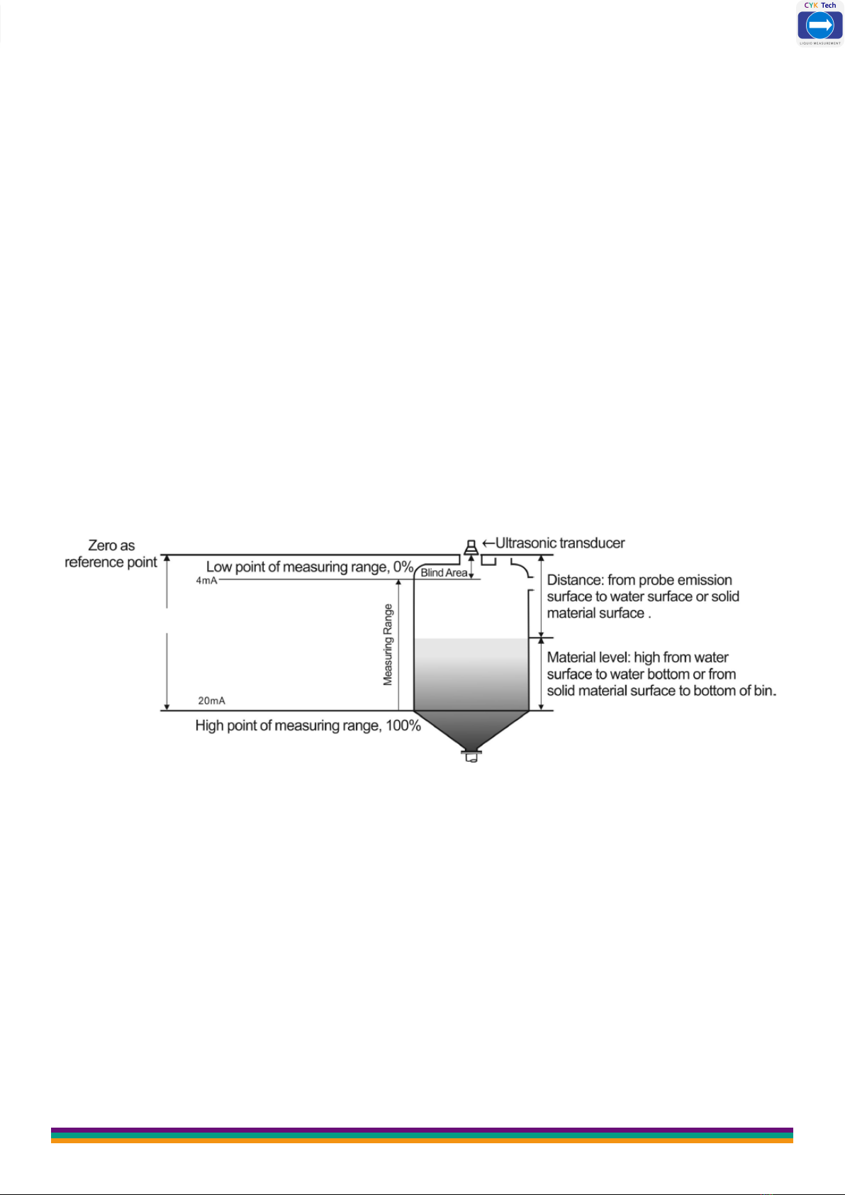
2.4 Diagram of distance and material level measurement ………………… 7
2.5 Anti-interference Measures ……………………………………………………… 8
Chapter 3: Main Technical Parameter ……………………………………………………… 9
Power Consumption …………………………………………………………………………… 10
Chapter 4: Installation Guide ………………………………………………………………... 11
4.1 Installation Dimension of Level Meter …………………………………… 11
4.1.1 Standard Remote Type Ultrasonic Level Meter ……………… 11
4.1.2 Enhanced Compact Type Ultrasonic Level Meter ………………… 11
4.2 Installation Guide ………………………………………………………………………... 13
4.2.1 Understand Terminology ……………………………………………………... 13
4.2.2 Select Measuring Range ……………………………………………………... 14
4.2.3 Installation of Thread at the Bottom …………………………………… 16
4.2.4 Top Thread Installation-Hoisting Installation ………………………… 17
4.2.5 Liquid Measurement ………………………………………………………………… 17
4.3 Solid Measurement ………………………………………………………………… 22
4.3.1 Flange Installation ………………………………………………………………… 22
4.3.2 Installation via Nipple Joint ……………………………………………………… 23
4.3.3 Doorframe Installation ……………………………………………………… 23
4.3.4 How to Extend the Connecting Pipe for Measurement ……… 24
4.3.5 Installation Should Avoid False Echo …………………………………… 27
4.4 Electric Wiring Diagram ………………………………………………………………… 32
4.4.1 Electric Wiring Diagram Single-Probe Remote-Type ………………… 33
4.4.2 Wiring Diagram of Compact Type ……………………………………………… 35
Chapter 5: Settings …………………………………………………………………………………… 37
5.1 Introduction of Interface of Operation Mode ………………………… 37
Chapter 6: Menu Interface & Operating Instructions …………………………………… 38
Chapter 7: Trobleshooting …………………………………………………………………………… 47
Chapter 8: Fault Causes at Site According to Echo Pattern ………………………… 48
8.1 Resonance …………………………………………………………………………………… 48
8.2 Liquid Enters the Blind Area of Ultrasonic Level Gauge ………………… 49
8.3 Electromagnetic Interference ……………………………………………………… 50
8.4 Effects of Connecting Pipe to Measurement …………………………………… 52
Chapter 9: Modbus Communication Protocol V1.4 Version ………………………… 53

CYK Tech
C h a p t e r 1 : P r o d u c t I n t r o d u c t i o n
www.ceyeko.com
Page 5
Ultrasonic level meter (for material and liquid level measurement) is a non-
contact highly reliable and cost-effective material level measuring instrument
which is easily installed and maintained. It can meet most of the material level
measurement requirements without touching the medium. It is a new generation
ultrasonic level meter with fully independent property rights developed by the
company via years of hard work.
Chapter 2: Operating Instructions for Simple Settings
As the meter installation site environment is different, the basic information of
measurement to be done must be learnt before the operation of the ultrasonic le-
vel meter, such as the measuring range, zero point, full scale and site conditions.
Therefore, the meter must be set before measurement.
Others: please do not modify probe selection, parameter correction and algo-
rithm selection without permission.
Normally the ultrasonic level meter produced by us shall be installed as per the
installation requirements of the manual and after that, the equipment can be nor-
mally used only after the following several parameters are set.
There are three buttons on the panel, via which the meter can be adjusted. The
measured values are displayed on the LCD screen after the adjustment.
SET
Enter Menu Item Exit Menu Item Confirm Parameter Modification
Move Cursor Modify Parameter Choose Menu Item

CYK Tech
www.ceyeko.com
Page 6
2.1 Enter the Menu
After power-on display of the meter, long press the set button (SET) for 2s to
enter in the main menu.
The menu modes include expert setting mode and simply setting mode.
The menu query table of simple setting mode is as shown in the below.
The menu query table of expert setting mode is shown in “VI. Menu Interface &
Operating Instructions: ”.

CYK Tech
www.ceyeko.com
Page 7
2.2 Select Measuring Mode:
Measuring modes are divided into distance measuring mode and material level
measuring mode. And the factory default is material level measurement.
2.3 Input probe height Value :
Input probe height value to “reference zero point” (probe height is the distance from
probe emitting surface to tank bottom or pool bottom).
2.4 Diagram of distance and material level measurement
❶ Under distance measuring mode, setting of reference zero point is meaningless
and the positions of maximum of measuring range and minimum of measuring range
are as shown in Fig. 1.1
Distance Measurement Mode; measure the distance from probe emision surface to
water surface, output 4-20 mA corresponds to the variation of distance.
Fig. 1.1 Diagram of Distance Measurement

CYK Tech
www.ceyeko.com
Page 8
After the equipment is installed, it must be grounded separately, don’t use the com-
mon ground of the electrical box or instrument box.
Suggestion: When the ultrasonic level meter is connected to the frequency conver-
ter, PLC and other devices that have interference, an isolation transformer should
be added to the power supply part, and a signal isolator should be added to the sig-
nal part, and reliable grounding should be done.
The signal line must not be installed in the same slot with the power line and
the power line. It must be installed separately through a metal pipe, or instal-
led away from the power line and power line. Under the premise of not being
installed through the pipe, the distance from the power line and power line at
least 1 meter
2.5 Anti-interference Measures:
❷ Under material level measuring mode, the positions of reference zero point,
maximum of measuring range and minimum of measuring range are as shown in
Fig. 1.2
Level Measurement Mode; measure the distance from water surface to water bot-
Fig. 1.2 Diagram of Material Measurement Level
Low Point: the distance from the reference plane to this position. When the low
point of the range is higher than the reference plane, the value is positive, and
when it is lower than the reference plane, the value is negative. When the liquid
level is at this position, 4mA current is output.
High Point: the distance from the reference plane to this position. The value is
positive when the range high point is higher than the reference plane, and negative
when it is lower than the reference plane. When the liquid level is at this position,
20mA current is output.

CYK Tech
www.ceyeko.com
Page 9
C h a p t e r 3 : M a i n T e c h n i c a l P a r a m e t e r
Function Compact Type Remote Type
Measuring Range 5m, 10m, 15m, 20m, 30m,
40m, 50m, 60m
5m, 10m, 15m, 20m, 30m,
40m, 50m, 60m, 70m
Measurement
Accuracy 0.5%-1.0%
Resolution Ratio 3mm or 0.1% (whichever is greater)
Display English LCD
Analog Output
4-wire system, 4~20mA/ 510Ω
load
2-wire system, 4~20mA/ 250Ω
4~20mA/ 510Ω load
Relay Output
2 groups (i.e. AC 250V/ 8A or
DC 30V/ 5A) optional, state
programmable
2 groups for single channel and
4 groups for double channels
(optional) AC 250V/ 8A or DC
30V/ 5A, state programmable
Power Supply
Standard configuration: 24VDC
Optional: 220V AC+15% 50Hz
Customized: 12VDC
Standard configuration: 220V
AC+15% 50Hz
Optional: 24VDC 120mA
Customized: 12VDC
Ambient
Temperature
Display instrument: -20~+60ºC
Probe: -20~+80ºC
Communication RS485, RS232 communication (optional)
Ingress Protection Display Instrument: IP65, Probe: IP68
Probe Cable None 100m available, standard
configuration: 10m
Probe
Installation
Select type based on
measuring range and probe

CYK Tech
www.ceyeko.com
Page 10
Power
Consumption
(Remote Type )
The power supply of Remote type is 24V power and the electri-
city consumed for such type is 100mA without relay,
150mA with 2 relays, 200mA with 4 relays.
Specific power consumed is shown in below:
24V×100mA=2.4W for remote type without relay;
24V×150mA=3.6W for remote type with 2 relays;
24V×200mA=4.8W for remote type with 4 relays;
Power
Consumption
(Compact Type)
The integrated type with four-wire system is powered by 24V
power supply and its electricity consumed is 80mA without relay,
105mA with a relay and 150mA with 2 relays.
Specific power consumed is shown in below:
24V×80mA=1.92W for integrated type without relay;
24V×150mA=3.6W for integrated type with 2 relays;
Power
Consumption
(Compact Type)
The integrated type with two-wire system is powered by 24V
power supply. It cannot be equipped with relay and its electricity
consumed is 20mA.
Specific power consumed is shown in below:
24×20mA=0.48W for integrated type without relay;
Power Consumption
Ce manuel convient aux modèles suivants
1
Table des matières


