
Central Pneumatic 95014 Manuel utilisateur

PRESSURIZED ABRASIVE
BLASTER
Model
95014
ASSEMBLY AND OPERATING INSTRUCTIONS
Visit our website at: http://www.harborfreight.com
Read this material before using this product.
Failure to do so can result in serious injury.
SAVE THIS MANUAL.
Copyright©2006 by Harbor Freight Tools®. All rights reserved. No portion of this manual or any artwork
contained herein may be reproduced in any shape or form without the express written consent of Harbor
Freight Tools. Diagrams within this manual may not be drawn proportionally. Due to continuing improve-
ments, actual product may differ slightly from the product described herein. Tools required for assembly
and service may not be included.
For technical questions or replacement parts, please call 1-800-444-3353.
Revised Manual 10d
PRODUCT SPECIFICATIONS
SKU 95014 For technical questions, please call 1-800-444-3353 PAGE 2
SAVE THIS MANUAL
You will need this manual for the safety warnings and precautions, assembly, operating,
inspection, maintenance and cleaning procedures, parts list and assembly diagram. Keep
your invoice with this manual. Write the invoice number on the inside of the front cover.
Keep this manual and invoice in a safe and dry place for future reference.
UNPACKING
When unpacking, check to make sure that all the parts and accessories listed on pages
15 and 16 are included, and the product is intact and undamaged. If any parts are miss-
ing or broken, please call Harbor Freight Tools at the number shown on the cover of this
manual as soon as possible.
SAFETY WARNINGS AND PRECAUTIONS
1. Do not operate the Pressurized Abrasive Blaster if the Air Supply Valve
(18) does not turn the tool on or off. Any tool that cannot be controlled with its
Air Supply Valve is dangerous and must be replaced.
2. Keep work area clean. Cluttered areas invite accidents.
3. WARNING! Do not operate pneumatic equipment in explosive
atmospheres, such as in the presence of ammable liquids, gases, or
dust. Pneumatic equipment can create sparks which may ignite
ammables.
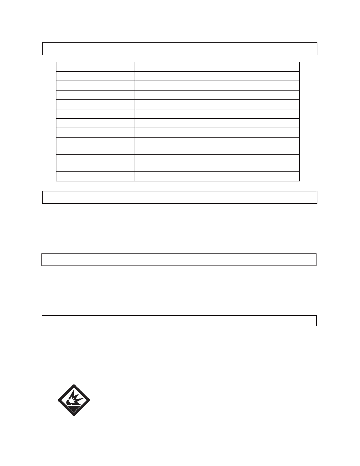
Item Description
Media Tank Capacity 110 Pounds or 20 Gallons
Working PSI 60 to 125 PSI
Air Consumption 6 CFM @ 60 PSI / 25 CFM @ 125 PSI (with 3/8” Hose)
Air Inlet Size 1/4”-18 NPT
Water Trap Type Push Button to Drain
Hose Dimensions 1/2” I.D. x 1” O.D. x 8’ - 6” Long
Pressure Gauge Indicator 0 <-> 150 PSI (White Face / Red Numbers)
Recommended Media
Type
Glass Bead / Silicon Carbide
Alumina / Walnut Shell / Brass Bead
Accessories Safety Hood / Blast Gun / Funnel
Ceramic Nozzles (2.0mm, 2.5mm, 3mm)
Overal Dimensions 35-1/2” High x 15” Diameter
REV 10d

SKU 95014 For technical questions, please call 1-800-444-3353 PAGE 3
4. WARNING! Always wear ANSI approved safety impact eye glasses under a full
face shield, a respirator, and heavy duty work gloves when operating the
Pressurized Abrasive Blaster. Also, wear heavy duty work boots, long trousers,
and long sleeve shirt.
5. Stay within air pressure capacity (60 to 125 PSI). Never operate the
Pressurized Abrasive Blaster above 125 PSI.
6. Keep children away. Children must never be allowed in the work area. Do not
let them handle equipment, tools, extension cords, or air hoses.
7. Store idle equipment. When not in use, the Pressurized Abrasive Blaster must
be stored in a dry location to inhibit rust. Always lock up the machine and keep
out of reach of children.
8. Use the right tool for the job. Do not attempt to force small equipent or
attachments to do the work of a larger industrial equipment and attachments.
There are certain applications for which this product was designed. It will do the
job better and more safely at the rate for which it was intended. Do not modify
this product, and do not use this product for a purpose for which it was not
intended.
9. Dress properly. Do not wear loose clothing or jewelry as they can be caught in
moving parts. Protective, electrically non-conductive clothes and non-skid foot-
wear are recommended when working. Wear restrictive hair covering to contain
long hair.
10. Do not overreach. Keep proper footing and balance at all times. Do not reach
over or across running tools or air hoses.
11. Disconnect air hose and release any built-up air pressure. Never service the
Pressurized Abrasive Blaster or disassemble with the air hose attached. Always
release any built-up air even after disconnecting hose. Disconnect the
Pressurized Abrasive Blaster when not in use.
12. Remove adjusting wrenches. Check that adjusting wrenches are removed
from the tool and work surface before attaching to an air source.
13. Stay alert. Watch what you are doing. Use common sense. Do not operate any
tool or equipment when you are tired.
14. Check for damaged parts. Before using any tool, any part that appears
damaged should be carefully checked to determine that it will operate properly
and perform its intended function. Check for alignment and binding of moving
parts, any broken parts, and any other condition that may affect proper operation.
Any part that is damaged should be properly repaired or replaced by a qualied
technician.

SKU 95014 For technical questions, please call 1-800-444-3353 PAGE 4
15. Replacement parts and accessories. This product is to be repaired and
serviced only by a qualied technician. When this product is serviced, only
identical replacement parts should be used. Use of any other parts will void the
warranty. Only use accessories intended for use with this tool. Approved
accessories are available from Harbor Freight Tools.
16. Do not operate this product if under the inuence of alcohol or drugs.
Read warning labels if taking prescription medicine to determine if your
judgement or reexes are impaired while taking drugs. If there is any doubt, do
not operate the tool.
17. Maintenance. The maintenance outlined in the “Maintenance” section should be
performed regularly. For your safety, this product should be serviced or repaired
regularly only by a qualied technician.
18. Compressed air only. Use clean, dry, regulated, compressed air at 65 to 125
PSI. Never use oxygen, carbon dioxide, combustible gases, or any other bottled
gas as a power source for this product.
19. Transport the Pressurized Abrasive Blaster safely. Always disconnect air
supply when moving the tool. Pull the tool by the handle to avoid tipping.
20. Avoid working alone. If an accident happens, an assistant can bring help.
21. Maintain labels and nameplates on the Pressurized Abrasive Blaster.
These carry important information. If unreadable or missing, contact Harbor
Freight Tools for a replacement.
22. Maintain a rm grip on the Blast Gun when in use.
23. Never point the Blast Gun toward yourself, other people, or animals. Keep
all people and animals safely away from the work area.
24. Maintain a safe distance away from the object being sandblasted.
Whenever possible, sandblast the object at a 45 degree angle to minimize the
possibility of grit, dirt, and debris ricocheting directly backward toward your face
and body.
25. Industrial applications must follow OSHA requirements.
26. Whenever possible, perform a sandblasting test on a small area of the
object to be sandblasted. If necessary, adjust the distance to the object and/or
change the Nozzle of the Blast Gun for more effective results.
27. Make sure to read and understand all safety warnings and precautions as

outlined in the manufacturer’s manual for the object you intend to
sandblast.
28. Avoid unintentional starting. Make sure the Control Lever (42C) on the Blast
Gun is in its “OFF” or “CLOSED” position when the tool is not being used.
29. WARNING! Some dust created by power sanding, sawing, grinding, drilling,
and other construction activities contain chemicals known (to the State of
California) to cause cancer, birth defects, or other reproductive harm.
Some examples of these chemicals are:
* Lead from lead-based paints,
* Crystalline silica from bricks, cement, and other masonry products,
* Arsenic and chromium from chemically treated lumber.
(California Health & Safety Code 25249.5, et seq.)
30. WARNING! Abrasive blasting with media containing crystalline silica
can cause serious or fatal respiratory disease. Exposure to crystalline silica
may cause silicosis (a serious lung disease), cancer, and death. Exposure to
aluminum oxide (a dust generated from material removing processes) can result
in eye, skin, and breathing irritation. Always use an ANSI approved respirator,
safety impact eye glasses, and a full face shield. Avoid skin exposure. Proper
ventilation in the work area is required. Read and understand the ten
recommended measures below to reduce crystalline silica exposure in the
workplace and prevent silicosis and silicosis related injuries and deaths.
The following ten measures are recommended to reduce crystalline silica
exposures in the workplace and prevent silicosis and silicosis related
injuries and deaths:
1. Prohibit silica sand (or other substances containing more than 1%
crystalline silica) as an abrasive blasting material and substitute less
hazardous materials.
2. Conduct air monitoring to measure worker exposures.
3. Use containment methods such as blast-cleaning machines and cabinets
to control the hazard and protect adjacent workers from exposure.
4. Practice good personal hygiene to avoid unecessary exposure to silica
dust.
5. Wear washable or disposable protective clothes at the worksite. Shower,
and change into clean clothes before leaving the worksite to prevent
contamination of cars, homes, and other work areas.
SKU 95014 For technical questions, please call 1-800-444-3353 PAGE 5

6. Use respiratory protection when source controls cannot keep silica
exposures below the recommended levels.
7. Provide periodic medical examinations for all workers who may be
exposed to crystalline silica.
8. Post signs to warn workers about the hazard and to inform them about
required protective equipment.
9. Provide workers with training that includes information about health
effects, work practices, and protective equipment for crystalline silica.
10. Report all cases of silicosis to State health departments and to OSHA or
the Mine Safety and Health Administration (MSHA).
31. WARNING! The brass components of this product contain lead, a chemical
known to the State of California to cause birth defects (or other reproductive
harm). (California Health & Safety code 25249.5 , et seq.)
32. WARNING! The warnings, cautions, and instructions discussed in this
instruction manual cannot cover all possible conditions and situations that may
occur. It must be understood by the operator that common sense and caution
are factors which cannot be built into this product, but must be supplied by the
operator.
SAVE THESE INSTRUCTIONS
SKU 95014 For technical questions, please call 1-800-444-3353 PAGE 6
SKU 95014 For technical questions, please call 1-800-444-3353 PAGE 7
ASSEMBLY INSTRUCTIONS
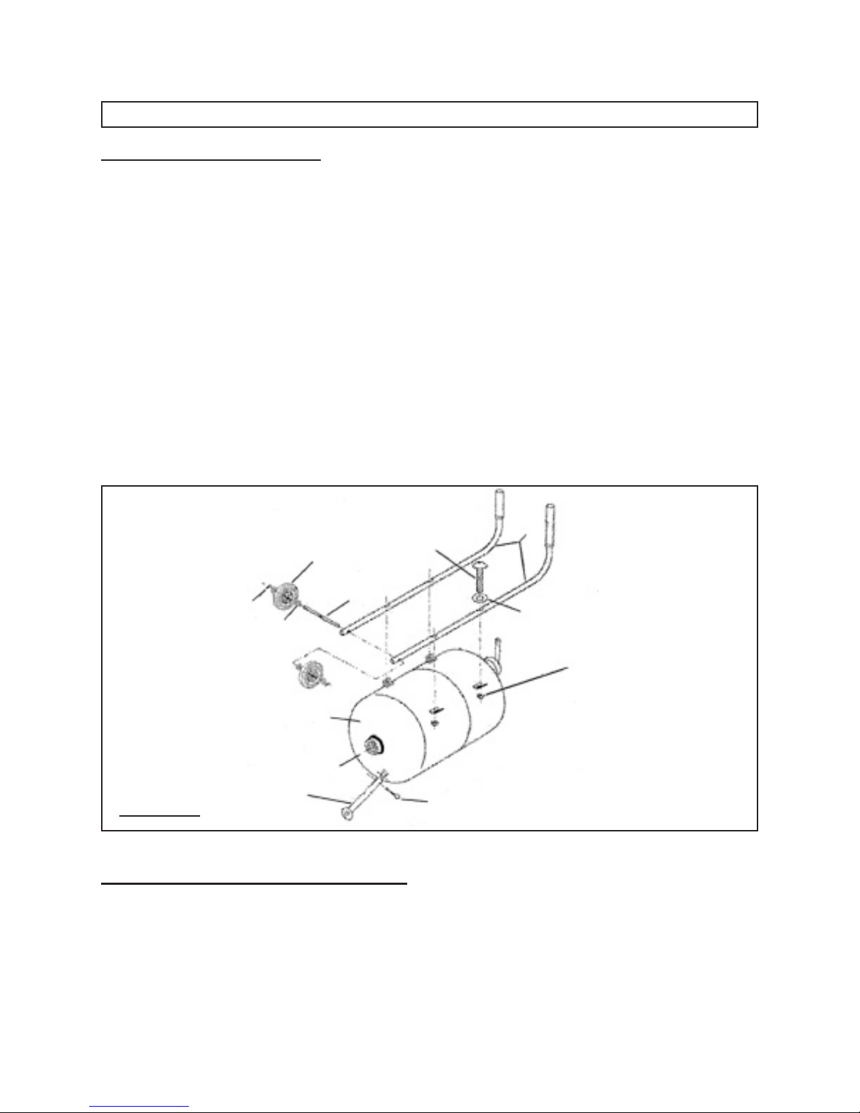
To Attach The Handle Bars:
1. To attach the two Handle Bars (6) to the Tank (1), lay the Tank on a at, level
surface with its Handle Bar mounting brackets facing up. (See Figure B.)
2. The Handle Bars (6) are labeled “Left” and “Right”. Align the holes in the left
Handle Bar with the Handle Bar mounting brackets on the left side of the Tank
(1). (See Figure B.)
3. Place a Washer (50) onto each of the four Handle Bar mounting Screws (8).
Insert a Screw through each of the holes in the Handle Bar and Handle Bar
mounting brackets. Then, screw a Hex Nut (9) onto each of the Screws and
rmly tighten. (See Figure B.)
4. Repeat Steps #2 and #3 for the right Handle Bar (6) to the Tank (1).
(See Figure B.)
FIGURE B
6
8
50
9
3
4
1
5
51
2
3
To Attach The Wheels And Front Foot:
1. Locate the two Wheels (2), three Cotter Pins (3), Wheel Axle (5), four Wheel
Washers (51), and Front Foot (4).
2. Slide the Wheel Axle (5) through the axle holes located at the bottom of the two
Handle Bars (6). (See Figure B.)

SKU 95014 For technical questions, please call 1-800-444-3353 PAGE 8
3. Slide a Wheel Washer (51) onto each end of the Wheel Axle (5).
(See Figure B.)
4. Place a Wheel (2) onto each end of the Wheel Axle (5). Then, slide a Wheel
Washer (51) onto each end of the Wheel Axle. (See Figure B.)
5. Insert a Cotter Pin (3) through the holes in each end of the Wheel Axle (5).
Then, bend the Cotter Pins to secure the Wheels (2) to the Wheel Axle.
(See Figure B.)
6. Roll the Pressurized Abrasive Blaster over so that the Handle Bars (6) are facing
down.
7. Align the holes of the Front Foot (4) with the holes in the foot mount on the front
side of the Tank (1). (See Figure B.)
8. Insert a Cotter Pin (3) through the holes and bend it to secure the Front Foot (4)
in place. (See Figure B.)
To Attach The Abrasive Hose And Blast Gun:
1. IMPORTANT: Make sure to use pipe thread sealer tape (not included) on all
threaded joints and ensure all joints are securely tightened.
2. Locate the Abrasive Hose (24), Blast Gun, and two Hose Clamps (23).
3. Slide one Hose Clamp (23) onto each end of the Abrasive Hose (24). Do not
tighten yet. (See Figure C.)
4. Slide one end of the Abrasive Hose (24) onto the Hose Adapter (49C) of the Blast
Gun. Then, rmly tighten the Hose Clamp (23). (See Figure C.)
1
BLAST GUN
49C 23
24
22
FIGURE C

5. Slide the other end of the Abrasive Hose (24) onto the Abrasive Outlet Manifold
(22). Then rmly tighten the Hose Clamp (23). (See Figure C.)
OPERATING INSTRUCTIONS
Abrasive Selection:
1. The type of media chosen will greatly inuence the amount of time needed to
clean a particular surface area.
2. Sandblasting media include silicon carbide, glass bead, walnut shell, brass bead,
and alumina.
3. If you decide to reuse media, remember, it does wear out. The sharp edges
become rounder and are less effective. At that point you should replace the tank
of media you are using.
To Load Media Into The Tank:
1. WARNING! Never service the Pressurized Abrasive Blaster or disassemble
with the air hose attached. Always release any built-up air even after
disconnecting the hose.
2. WARNING! Always wear ANSI approved safety impact eye glasses under a
full face shield, a respirator, and heavy duty work gloves when operating the
Pressurized Abrasive Blaster. Also, wear heavy duty work boots, long trousers,
and long sleeve shirt.
3. Make sure the media used is dry to avoid clogging the Abrasive Control Valve
(18B), Abrasive Outlet Manifold (22), or Abrasive Hose (24).
4. Turn the Air Supply Valve (18) to the “OFF” position.
(See Figure D, next page.)
5. Check the Pressure Gauge (15) to make sure it reads “0” pressure.
(See Figure D.)
6. Unscrew and remove the Tank Filler Cap (12). Insert the accessory Funnel (29)
into the Tank (1) opening. Then pour the media into the Tank, making sure to
pour enough into the Tank to do the job at hand. Then, replace the Tank Filler
Cap. NOTE: If this is a large job, ll the Tank only 3/4 full and reload as needed
to nish the job. (See Figure D.)
SKU 95014 For technical questions, please call 1-800-444-3353 PAGE 9
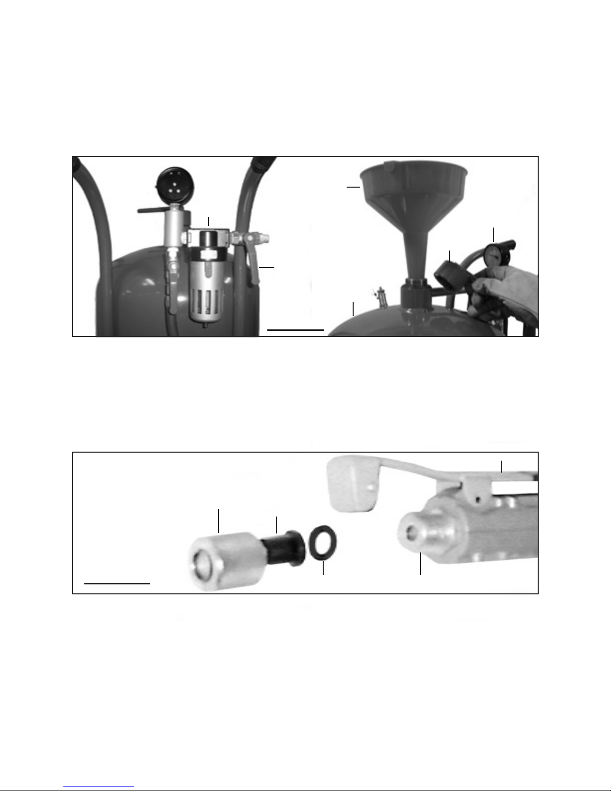
7. IMPORTANT TIP: If the humidity is 90 to 100%, the Water Trap (17) will not be
able to trap all of the moisture in a 3/4 full Tank (1). It is recommended to reduce
the amount of media, load more frequently, and empty the Water Trap more
often. This will reduce the possibility of clogging the bottom of the Tank or the
line. (See Figure D.)
SKU 95014 For technical questions, please call 1-800-444-3353 PAGE 10
8. Depending on the size (diameter) of the media, install the proper size Ceramic
Nozzle (37C) onto the Blast Gun. To do so, unscrew and remove the Nozzle Cap
Nut (39C). Position the Nozzle Gasket (36C) against the Adapter (35C).
Position the proper Ceramic Nozzle (2.0mm, 2.5mm, or 3.0mm) against the
Nozzle Gasket. Then screw the Nozzle Cap Nut back onto the Adapter to secure
the Nozzle Gasket and Ceramic Nozzle in place. (See Figure E.)
WATER TRAP
(17)
FUNNEL
(29)
PRESSURE GAUGE
(15)
TANK
FILLER CAP
(12)
TANK
(1)
AIR SUPPLY VALVE
(18)
FIGURE D
FIGURE E
CERAMIC NOZZLE
(37C)
NOZZLE GASKET
(36C)
NOZZLE CAP NUT
(39C)
ADAPTER
(35C)
CONTROL LEVER (42C)
Table des matières
Autres manuels Central Pneumatic Nettoyeur haute pression


