Centech 67980 Manuel d'installation


58B Table of Contents
1. Safety Instructions.............................................................................1
1.1 Work Area Safety....................................................................1
1.2 Electrical Safety.......................................................................1
1.3 Personal Safety ........................................................................2
2. Description, Specifications and Tool Components..........................3
2.1 Description...............................................................................3
2.2 Specifications ...........................................................................3
2.3 Accessories Included ...............................................................4
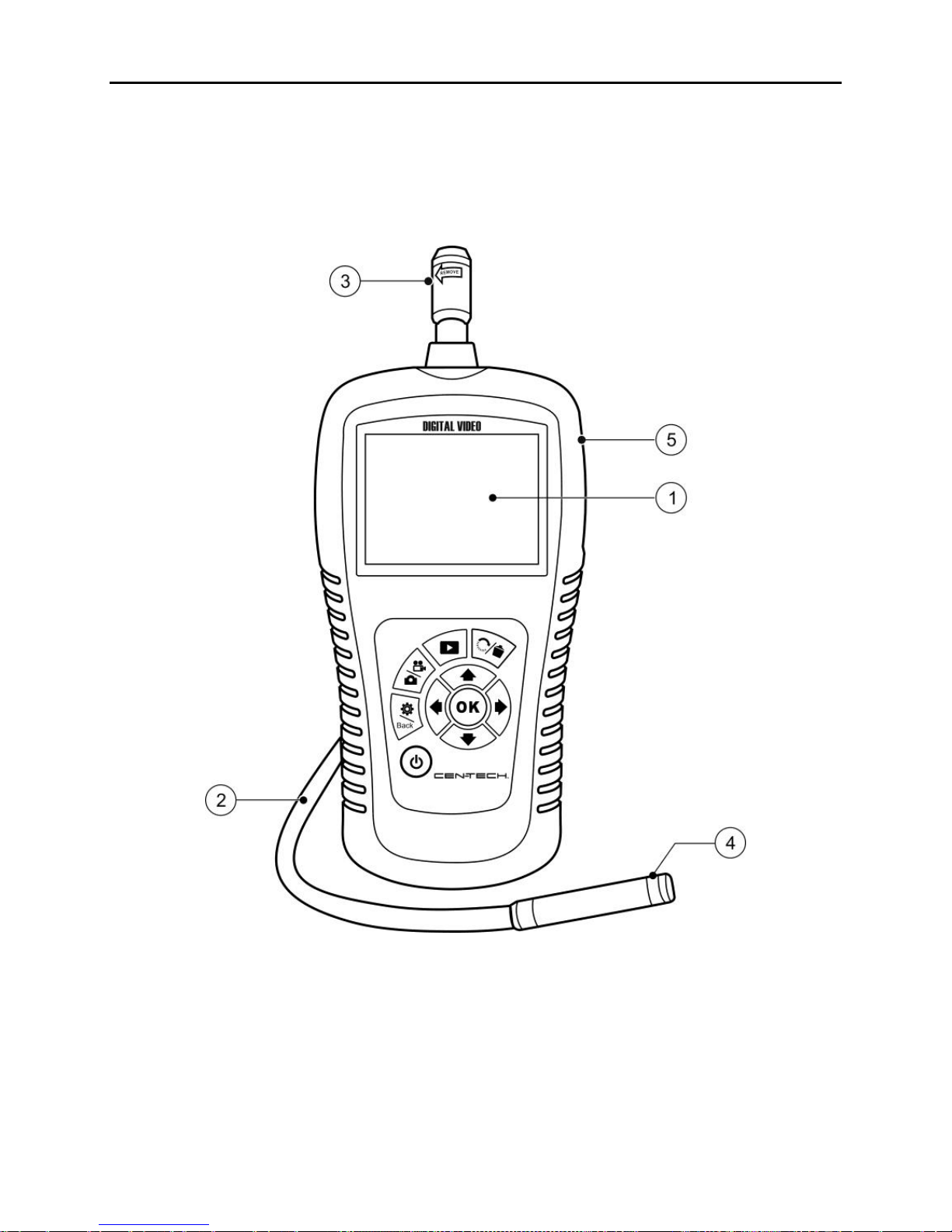
2.4 Tool Components.....................................................................5
2.5 Buttons and Ports....................................................................6
3. Installation and Connection..............................................................8
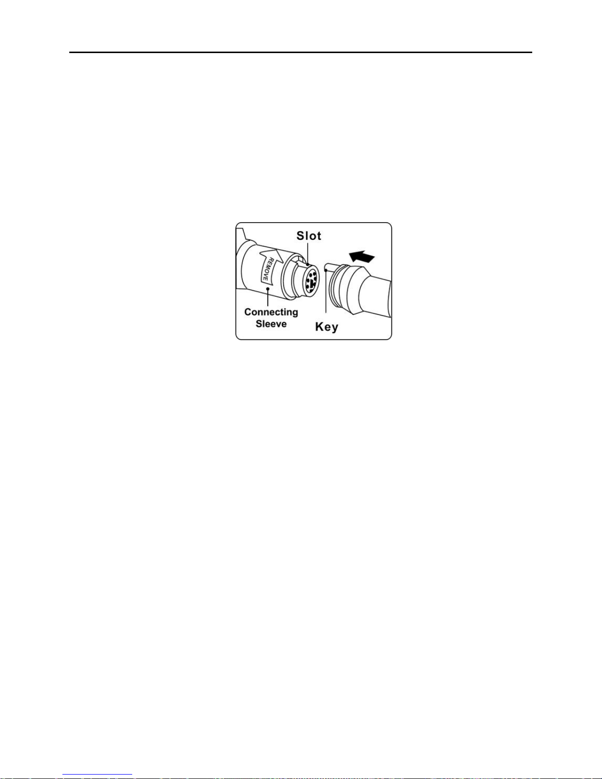
3.1 The Imager Head and Cable Installation..............................8
3.2 Accessories Installation...........................................................9
3.3 SD Card Installation..............................................................10
3.4 USB Cable Connection..........................................................10
3.5 Video-Out Cable Connection................................................11
3.6 Earphone Connection............................................................11
4. Battery Charging Precautions........................................................12
4.1 Battery Charging Safety .......................................................12
4.2 Battery and Charger Specifications.....................................12
4.3 Charger Inspection................................................................13
4.4 Battery Charging Procedures...............................................13
5. Operation Instructions....................................................................15
5.1 Basic Operation .....................................................................15
5.2 Operation Precautions ..........................................................16
5.3 Tool Inspection ......................................................................17
5.4 Tool and Work Area Set-Up.................................................18
5.5 On Screen Navigation............................................................20
5.6 Icons........................................................................................27
6. Troubleshooting...............................................................................35
7. Parts List and Diagram...................................................................36

Safety Instructions WorkArea Safety
1
1. Safety Instructions
IMPORTANT: To prevent electric shock, fire and/or personal injury
or damage, read this user’s manual first and observe the following
safety instructions.
6B1.1 WorkArea Safety
60BAlways perform automotive testing in a safe environment.
61BKeep your work area clean and well lit. Cluttered benches and
dark areas may cause accidents.
62BKeep clothing, hair, hands, tools, test equipment, etc. away from
all moving or hot engine parts.
63BOperate the tool in a well-ventilated work area.
64BDo not operate the tool in explosive atmospheres, such as in the
presence of flammable liquids, gases, or heavy dust.
65BKeep a fire extinguisher suitable for gasoline/chemical/electrical
fires nearby.
66BDo not use the tool around corrosive chemicals which can ruin
the photo quality.
67BKeep bystanders, children and visitors away while operating the
tool.
68BKeep the tool dry, clean, free from oil, water and grease. Use a
mild detergent on a clean cloth to clean the outside of the tool
when necessary.
7B1.2 Electrical Safety
70BAvoid body contact with grounded surfaces such as pipes,
radiators, ranges and refrigerators.
71BDo not expose the tool to rain or wet conditions. Water entering
the tool will increase the risk of electric shock.
72BDo not abuse the cord. Never use the cord for carrying, pulling,
or unplugging the tool. Keep cord away from heat, oil, sharp
edges or moving parts.
74BIf operating the tool in a damp location is unavoidable, use a
ground fault circuit interrupter (GFCI) to protect supply.

Safety Instructions Personal Safety
2
1.3 Personal Safety
75BDo not use the tool while tired or under the influence of drugs,
alcohol, or medications. A moment of interruption can result in
serious personal injury.
76BDo not over-reach. Keep proper footing and balance at all times.
Proper footing and balance enables better control of the tool in
unexpected situations.
77BAlways wear safety eye protection that meets ANSI standards.
78BDo not wear loose clothing or jewelry. Keep your hair, clothing,
and gloves away from moving parts. Loose clothes, jewelry, or
long hair can be caught in moving parts.
79BDo not place the tool on any unstable cart or surface. The tool
may fall causing serious injury to a person or serious damage to
the tool itself.
80BNever spill liquid on the display units. Liquid increases the risk
of electric shock and damage to the tool.
81BDo not use the tool for personal or medical use in any way.
82BThe product is not shock-resistant. Do not use it as a hammer or
drop it.

Description, Specification and Tool Components Description
3
2. Description, Specifications and Tool
Components
9B2.1 Description
83BThe Inspection Camera is an ideal and powerful tool for inspecting
difficult-to-reach areas normally hidden from sight. It is a completely
digital platform that features the function of capturing and recording
photos and videos either on its internal memory or on removable SD
cards (not included). The ergonomic tool not only features a 3.5" full
color LCD screen, multi-language interface and viewing capacity as
close as 1" with crystal clear output, but also offers the capacity to
view real time images directly connected to a TV and upload captured
photos and videos to a PC. Accessories (magnet, hook and mirror) are
included to attach to the imager head to provide application flexibility.
10B2.2 Specifications
84BRecommended use
85BIndoor
86BOptimal viewing
Distance
87B1" to 14"(2.5cm to 35.6cm)
98BImage capture
99B640 x480
88BScreen type
display
89B3.5" TFT LCD
90BDisplay resolution
91B320311B310B x 240
92BPower supply
93BBBuilt-in rechargeable lithium-ion battery
pack (3.7 Volt)
94BTested battery life
95B5-6 hours of continuous use
96BDimensions
9255 x 108 x 36mm (10"x 4.25"x 1.42")
98BWeight
99BNet: 0.6 kg (1.3 lbs);
Gross: 2.3 kg (5.1lbs)
98BRecording
medium
99BInternal memory or SD card (SD card is
optional and not included)

Installation and Connection Description
4
98BImage controls
99BZoom, low light vision
98BLighting
99BFully adjustable LED
102BCable reach
103B11m (3') -- expandable to 6m (19')
w/optional extensions (not included)
98BImager head
99B8.5mm (0.33")
106Bwaterproof
107BImager head and cable to 3m (10')
102BAdditonal ports
103BUSB, video out and earphone ports
Operating temp.
Main unit: 32°F to 113°F (0°C to 45°C);
Cable: 14°F to 176°F (-10°C to 80°C)
106BStorage temp.
107B-4°F to 158°F (-20°C to 70°C)
306B104BOperating
humidity
105B5% - 95% non-condensing (display unit)
98BVideo output
99BRCA
11B2.3 Accessories Included
1) Protective carrying case
2) User’s Manual
3) Imager head and cable (8.5mm)
4) Magnet, hook and mirror
5) Charger
6) USB cable
7) Video-out cable

Installation and Connection Tool Components
5
2.4 Tool Components
110B Note: Because of continuing improvements, actual product may
differ slightly from photo.
The Inspection Camera comes with the following items:
Fig. 1
1) LCD Screen –Indicates still images and videos.
2) 112BCable –Connects to the tool while in use.
3) 113BCable Connector –Connects the display unit to the imager head
and cable.
4) 114BImager Head –Connects to the cable to view real-time images.
5) 115BRubber Boot –Protects the tool casing.

Installation and Connection Tool Components
6
Fig. 2
6) Accessory Magnet –Picks up small metal objects such as
dropped rings or screws on the floor.
7) 117BAccessory Hook –Unclogs obstacles and picks up wires in pipes
or confined areas.
8) 118BAccessory Mirror –Helps users look around corners and see
inside difficult to reach areas.
12B2.5 Buttons and Ports
Fig. 3
A. Power Button –Turns on/off the tool.
B. 120BSetting/Back Button –Moves to the primary settings screen, or
when pressed again, returns to the last viewed screen.
C. Camera/Video Button –Captures photos or videos.
D. 122BPlay Button –Changes to play mode to play captured photos
and videos.

Installation and Connection Tool Components
7
E. 124BTrash Can/Reverse Button –Deletes captured photos and
videos in the play mode. Pressing again will control the direction
of the real-time image and video in the live screen. The real-time
image and video will do a horizontal reverse or a vertical reverse.
F. LEFT Arrow LED Lighting Adjusting Button –Uses left
arrow button to decrease LED brightness in the camera mode.
G. RIGHT Arrow LED Lighting Adjusting Button –Uses right
arrow button to increase LED brightness in the camera mode.
H. 126BUP Arrow Zoom Adjusting Button –Uses up arrow button to
zoom in while in the camera mode.
I. DOWN Arrow Zoom Adjusting Button –Uses down arrow
button to zoom out while in the camera mode.
J. DC Power Source Port –Connects the tool to the supplied
charger for battery charging.
K. 128Video-out Port –Connects the tool to a TV with the supplied
video-out cable to view the real-time image.
L. Earphone Port –Connects an optional earphone/microphone.
M. 130BCharging Indicator Light –When the battery is charging, the
charging indicator light is red. When the battery is fully charged,
the charging indicator light changes to green.
N. 131BMini USB Port –Connects the tool to a computer with the
supplied USB cable to upload and view captured photos and
videos.

Installation and Connection Accessories Installation
8
3. Installation and Connection
14B3.1 312BThe Imager Head and Cable Installation
143BTo use the tool, the imager head and cable must be connected to the
display unit. To connect the cable to the display unit, make sure the
key and slot (Fig. 4) are properly aligned. Once they are aligned, slide
the connecting sleeve up to the threads on the cable, and finger-tighten
to hold the connection firmly in place.
Fig. 4
Table des matières
Autres manuels Centech Instrument analytique
Manuels Instrument analytique populaires d'autres marques

EXTOL PREMIUM
EXTOL PREMIUM 8820043 Instructions d'installation et d'utilisation

RIDGID
RIDGID SeeSnake Compact Manuel utilisateur

Teledyne
Teledyne 3000PA Manuel utilisateur

YDLIDAR
YDLIDAR TIA Manuel utilisateur

Olympus
Olympus IPLEX FX Series Manuel utilisateur

Bosch
Bosch GLM 50 C Professional Manuel utilisateur


