CEMB SM825 Manuel utilisateur

REV. 01 1 / 28
SM825 ver.T
Semi-Automatic Car
Tire Changer Manual

REV. 01
2 / 28
PRINTING CHARACTERS AND SYMBOLS
Throughout this m nu l, the following symbols nd printing ch r cters re used to f cilit te re ding:
Indic tes the oper tions which need proper c re
Indic tes prohibition
Indic tes possibility of d nger for the oper tors
BOLD TYPE
Import nt inform tion
WARNING: befo e ope ating the lift and ca ying out any adjustment, ead
ca efully chapte 7 “installation” whe e all p ope ope ations fo a bette
functioning of the lift a e shown.

REV. 01
3 / 28
CONTENTS
1 INTRODUCTION 4
2 GENERAL INFORMATION 6
3 TRANSPORT, UNPACKING AND STORAGE 9
4 INSTALLATION 10
5 OPERATION 16
6 INFLATING 20
7 MAINTENANCE 22
8 TROUBLESHOOTING 24
9 ELECTRIC AND PNEUMATIC DIAGRAM 25

REV. 01
4 / 28
CHAPTER 1 – INTRODUCTION
1.1 INTRODUCTION
Th nk you for purch sing product from the line of tire ch ngers. The m chine h s been
m nuf ctured in ccord nce with the very best qu lity principles. Follow the simple instructions
provided in this m nu l to ensure the correct oper tion nd long life of the m chine. Re d the entire
m nu l thoroughly nd m ke sure you underst nd it.
1.2 TYRE CHANGER IDENTIFICATION DATA
A complete description of the “Tire Ch nger Model” nd the “Seri l number” will m ke it e sier for
our technic l ssist nce to provide service nd will f cilit te delivery of ny required sp re p rts. For
cl rity nd convenience, we h ve inserted the d t of your tire ch nger in the box below. If there is
ny discrep ncy between the d t provided in this m nu l nd th t shown on the pl te fixed to the tire
ch nger, the l tter should be t ken s correct.
1.3 MANUAL KEEPING
For proper use of this m nu l, the following is recommended:
• Keep the m nu l ne r the lift, in n e sily ccessible pl ce.
• Keep the m nu l in n re protected from the d mp.
• Use this m nu l properly without d m ging it.
• Any use of the m chine m de by oper tors who re not f mili r with the instructions nd
procedures cont ined herein sh ll be forbidden.
This m nu l is n integr l p rt of the m nu l: it sh ll be given to the new owner if nd when the
m chine is resold.
The illust ations have been made out of p ototypes pictu es. It is the efo e
possible that some pa ts o components of standa d p oduction diffe f om those
ep esented in the pictu es.
1.4 GENERAL SAFETY PRECAUTIONS
The ti e change may only be used by specially t ained and autho ized expe t
pe sonnel.
LOGO
Type:
Volt Amp Kw
Ph Hz
Ye r of m nuf cturing:
Air supply: 8-10 b r (116 – 145 PSI)

REV. 01
5 / 28
• Any t mpering or modific tion to the equipment c rried out without the m nuf cturer’s prior
uthoriz tion will free him from ll responsibility for d m ge c used directly or indirectly by
the bove ctions.
• Removing or t mpering with s fety devices immedi tely inv lid tes the gu r ntee.
• The tire ch nger comes complete with instruction nd w rning tr nsfers which re designed
to be long-l sting. If they should for ny re son be d m ged or destroyed, ple se sk
immedi tely for repl cements from the m nuf cturer.
TO THE READER
Every effort h s been m de to ensure th t the inform tion cont ined in this m nu l is correct, complete
nd up-to d te. The m nuf cturer is not li ble for ny mist kes m de when dr wing up this m nu l nd
reserves the right to m ke ny ch nges due the development of the product, t ny time

REV. 01
6 / 28
CHAPTER 2 – GENERAL INFORMATION
2.1
INTENDED USE
• This Semi- utom tic tire ch nger h s been designed nd m nuf ctured exclusively for
removing nd mounting tires from/onto rims from 10" to 26" nd m ximum di meter of
1000 mm.
• In p rticul r THE MANUFACTURER c nnot be held responsible for ny d m ge c used
through the use of this tire ch nger for purposes other th n those specified in this m nu l, nd
therefore in ppropri te, incorrect nd unre son ble.
2.2 DESCRIPTION
G) Cl mps
I) Mounting he d
M) Mounting b r
N) Horizont l rm
P) Vertic l rm
Q) Air supply
R) Be d bre ker
S) Wheel support
T) Be d lifting lever
U) Cl mp control ped l
V) Cl mp control ped l
Z) Reverser control ped l
Y) Turnt ble
K) Locking lever
Fig . 1

REV. 01
7 / 28
2.3 DANGER WARNING SIGNS

REV. 01
8 / 28
2.4 TECHNICAL SPECIFICATION
Extern l locking rim dimension
12" - 26"
13" - 27"
14" - 28"
Intern l locking rim dimension
14" – 28”
15" - 29"
16" - 30"
M x. tire di meter 1200mm (47.5”)
M x tire width 470mm (18.5”)
Force on be d bre ker bl de (10 b r) 2500 kg
Working pressure 8 b r (116 psi)
Infl ting pressure device m x. 3.5 b r (50 psi)
Power supply volt ge
400V 3 Ph
230V 1Ph
110V 1PH
Motor power
0.55 (400V 3 ph single speed)
0.8/1.1 kw (400V 3ph double speed)
0.75 kw (230V 1ph)
1.1KW (110V 1ph)
Rot ting speed 7 – 14 rpm
M x spindle torch 1200 NM
Dimension 1140 x 1100 x 950
Net weight 240 kg STND
Noise level in working condition < 70 dB (A)

REV. 01
9 / 28
CHAPTER 3 – TRANSPORTATION, UNPACKING AND STORAGE
3.1 TRANSPORTATION
• The tire ch nger must be tr nsported in its origin l p ck ging nd kept in the position shown
on the p ck ge itself.
• The p ck ged m chine m y be moved by me ns of fork lift truck of suit ble c p city. Insert
the forks t the points shown in figure 3.
3.2 UNPACKING
• Remove the protective c rdbo rd nd the nylon b g.
• Check th t the equipment is in perfect condition, m king sure th t no p rts re d m ged or
missing. Use fig. 1 for reference.
If in doubt do not use the machine and contact you etaile .
3.3 STORAGE
In the event of stor ge for long periods of time, be sure to disconnect ll sources of power nd gre se
the cl mp sliding guides on the turnt ble to prevent them from oxidizing.
REV. 01
10 / 28
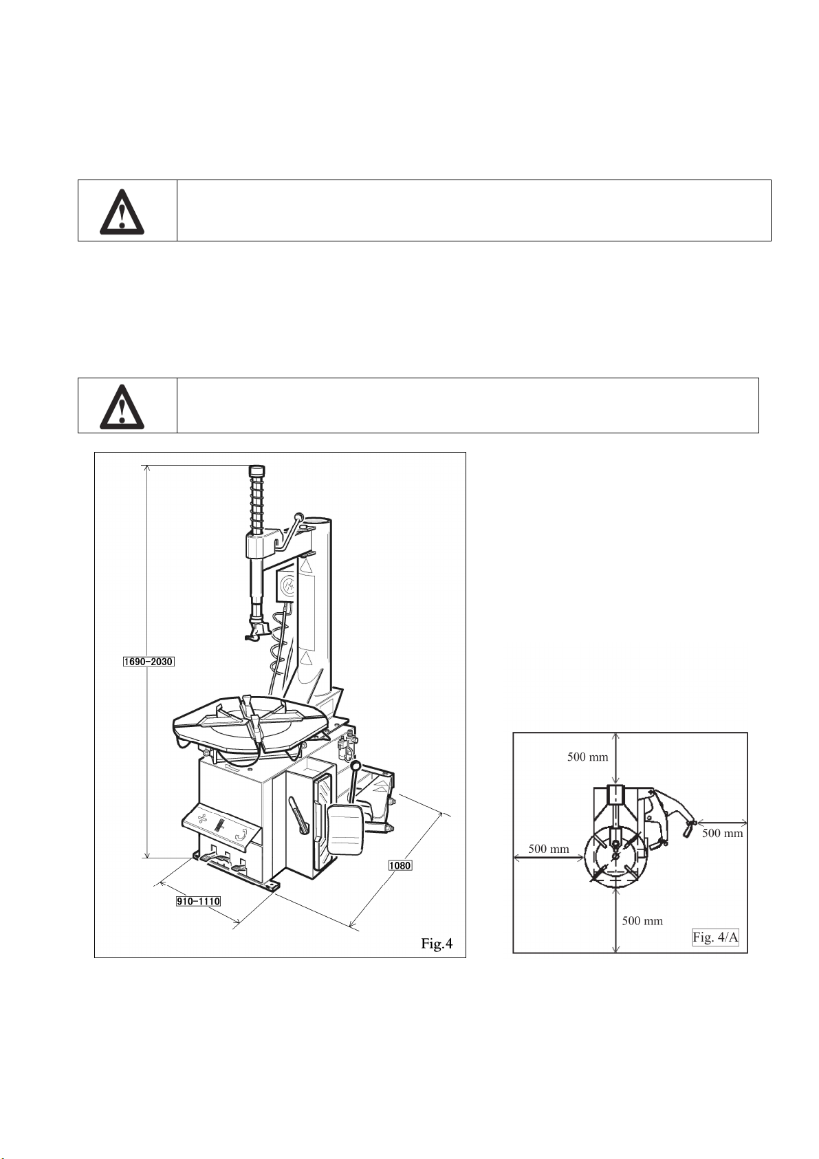
CHAPTER 4 – INSTALLATION
4.1 SPACE REQUIRED
When choosing the place of installation be su e that it complies with cu ent safety
at wo k egulations.
• The tire ch nger must be connected to the m in electric power supply nd the compressed ir
system. It is therefore dvis ble to inst ll the m chine ne r these power sources.
• The pl ce of inst ll tion must lso provide t le st the sp ce shown in pictures 4 - 4/A so s to
llow ll p rts of the m chine to oper te correctly nd without ny restriction.
• If the m chine is inst lled outside it must be protected by le n-to.
The ti e change with elect ic moto cannot be used in explosive atmosphe es,
unless it is a p ope ve sion.
Table des matières
Autres manuels CEMB démonte-pneus


Manuels démonte-pneus populaires d'autres marques


Coats
Coats 80C Manuel utilisateur

HENNESSY INDUSTRIES
HENNESSY INDUSTRIES Coats Rim Clamp X-Model Series Manuel utilisateur

Draper
Draper 78612 Manuel utilisateur

Aston Global
Aston Global ATC-5800 Mode d’emploi

HENNESSY INDUSTRIES
HENNESSY INDUSTRIES Coats CHD-4730-4730W Manuel

Butler
Butler NAV11N Manuel utilisateur