
Celona AP 20 Manuel utilisateur
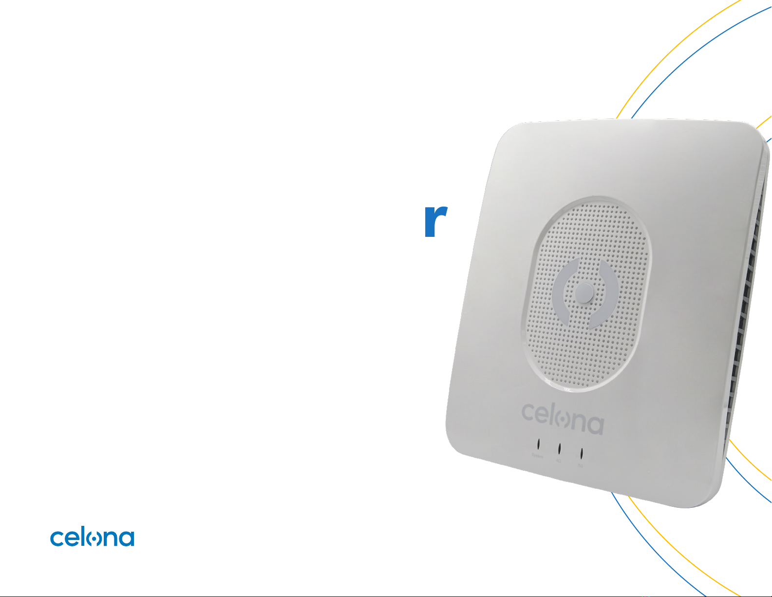
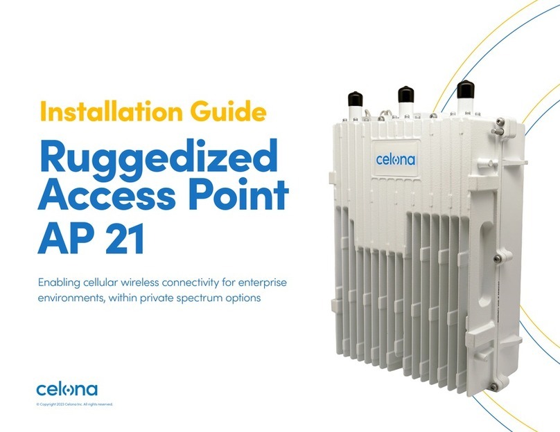
Installation Guide
Celona Indoor
Access Point
AP 20
Enabling cellular wireless connectivity for enterprise
environments, within private spectrum options
© Copyright 2023 Celona Inc. All rights reserved.

© Copyright 2023 Celona Inc. All rights reserved.
Installation Guide Celona Indoor Access Point AP 20 2
Contents
Introduction 3
About the AP 3
Package Contents 3
Ethernet ports 3
Power input 3
GPS 3
Status LEDs and Interfaces 3
Mounting 4
Installation Overview 4
Mounting the Access Point 4
Install on Prelude and Suprafine T-bar 5
Install on silhouette and interlude T-bar 7
Install on a wall 10
Powering the Access Point 12
Access Point Discovery and Provisioning 12 Configuring the Access Point 12
Solution Architecture 13
Celona AP 20 capabilities 13
Operations and Maintenance 14
Security 14
Phase and time synchronization 14
Data and voice connectivity 14
Power save mode 14
Radio access technology 15
Supported frequency band 15
Seamless session mobility 15
Coverage area 15
Transmit power 15
Supported system bandwidth 15
Troubleshooting 16
Contacting Support 16 Warranty 16

© Copyright 2023 Celona Inc. All rights reserved.
Installation Guide Celona Indoor Access Point AP 20 3
Package Contents
Verify that you have received the
items below. If any item is missing or
damaged, contact your Celona partner
or reseller for instructions.
• The Access Point
• Mounting bracket and screws
• PoE injector
Introduction
This document provides the necessary guidance to
help the user enable services on the Celona Indoor
Access Point AP 20 capable of private 5G connectivity.
Identity Color Status Description
System Blue
Steady on Power is on
OFF No power supply
4G Blue
Steady on Radios are up and transmitting
OFF Radios are non-operational
5G Blue
Steady on Radios are up and transmitting
OFF Radios are non-operational
About the AP
Celona AP 20 is an indoor 4G/5G NR access point as a
part of Celona’s 5G LAN solution portfolio, supporting
Sub-6 Ghz frequency bands (3.55–3.7 GHz). AP 20
oers highly deterministic performance over the air,
less than 10ms latency and exceptional coverage. With
an enterprise-ready operational model, Celona AP 20
access point is designed for mission-critical use cases
in indoor and semi-ruggedized environments. Like all
Celona access points, the AP 20 supports plug-and-play
deployment, remote provisioning, centralized cloud-
based management and seamlessly integrates into the
enterprise network.
Celona AP 20 is a fully integrated indoor access
point that can be used for 4G or 5G NR operation in
enterprise environments. The presence of both 4G
and 5G radios allows enterprises to future-proof their
infrastructure as the device ecosystem evolves from 4G
to 5G. Celona AP 20 is 3GPP Release 15 compliant 5G
NR access point and 3GPP Rel. 13 TDD compliant 4G LTE
Indoor Access Point that supports 2x2 MIMO, up to 256
QAM modulation, subcarrier space of 30 KHz and can
be ceiling or wall mounted.
Ethernet ports
The Celona AP 20 has 1/2.5 Gigabit Ethernet port.
Power input
Celona AP 20 supports IEEE 802.3bt Type 4 (PoE++)
connectivity. PoE++ can be provided by a PoE++
injector (AC to PoE power, included in the AP) or a
PoE++ capable switch. The drawn power is ≤ 71 W.
GPS
A Subminiature Version A (SMA) coaxial RF connector port is available for GPS. If obtaining GPS lock is
dicult, connecting a GPS puck to the Celona AP 20 may help achieve lock. The GPS puck is typically
placed closer to a window where there is line of sight visibility to the sky and a cable is extended from
the GPS puck to the SMA connector port for GPS on the Celona AP 20.
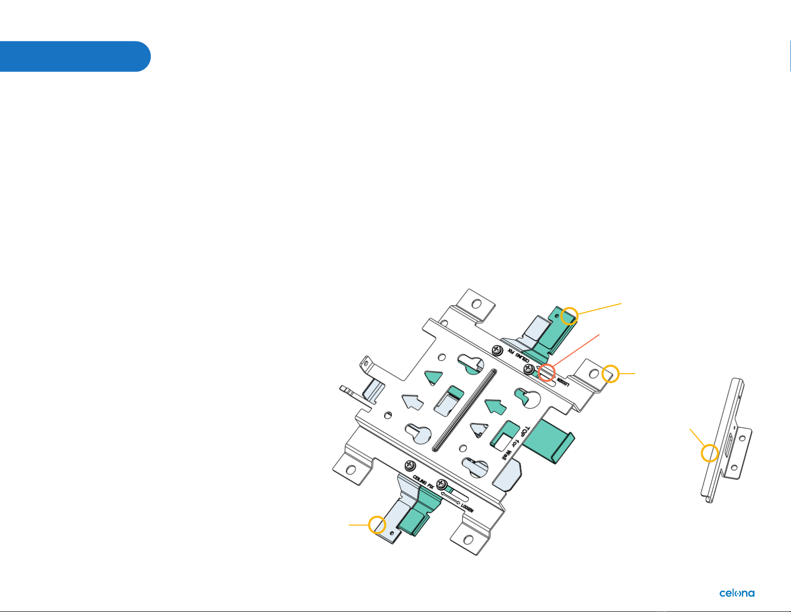
Status LEDs and Interfaces
The Celona AP 20 has 2 LEDs providing the following visual statuses for System, 5G
© Copyright 2023 Celona Inc. All rights reserved.
Installation Guide Celona Indoor Access Point AP 20 4
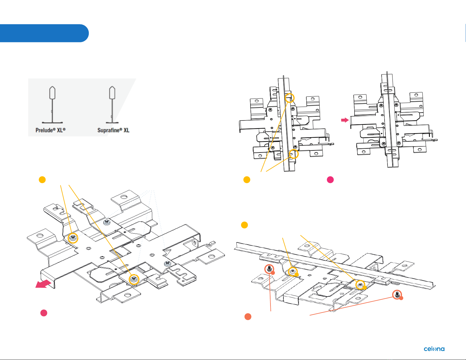
Main parts of mounting kit assembly
Active grid bracket
Pay attention
to install mark
Fixed grid bracket
Mounting kit
Bracket block x2
Installation Overview
The Celona AP 20 can be wall or ceiling mounted and has four omni-
directional internal antennas. Internal antennas are down-tilt toward
the front of the AP. Before you mount and deploy your access point, we
recommend that you perform a wireless design to determine the best
location to install your access point.
The AP requires an operational Celona Edge for discovery and network
service. Celona recommends installation and deployment of the Celona
Edge prior to installation of access points. Have the following information
about your wireless network design available:
• Locations for access point installation
• Mounting requirements for each location: suspended from a drop-
ceiling, surface mount on a hard ceiling, or on a flat horizontal surface
Installing the access point involves the following steps:
1. Mounting the Access Point
2. Powering the Access Point
3. Access Point Discovery and Provisioning
4. Configuring the Access Point
Mounting the Access Point
The Celona mount-kit supports several mounting methods, including
from a suspended drop- ceiling, hard surface ceiling, and on a flat
horizontal surface such as a wall. The standard mounting hardware
included with the AP supports these mounting methods.
Mounting
© Copyright 2023 Celona Inc. All rights reserved.
Installation Guide Celona Indoor Access Point AP 20 5
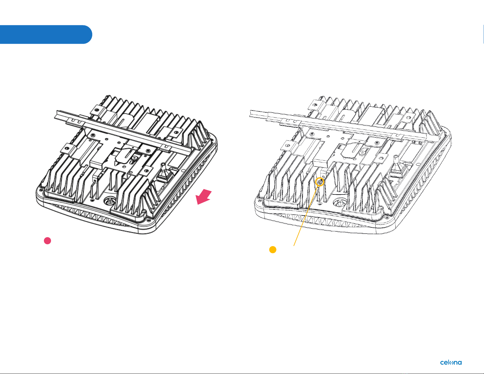
Install on Prelude and Suprafine T-bar
Mounting
Loosen these two M4*10 screws
Pull out the active grid bracket
in the arrow direction
Step 1: Loosen two screws and pull out the active grid bracket.
1
2
Screws M4*10
2
1
Step 2: Push the active grid bracket to hold the T-bar
Put the fixed grid bracket
to hold one side of T bar
Push the active grid bracket in the arrow direction to
clamp onto the other side of the T-bar
1 2
Step 3: Fix the active grid bracket and fasten the two
screws to prevent the mounting kit from slipping.
Fasten these two screws
M3*9 to prevent slipping
Tighten the two screws M4*10
to fix the active grid bracket
1
2
1
2
2
1
© Copyright 2023 Celona Inc. All rights reserved.
Installation Guide Celona Indoor Access Point AP 20 6
Mounting
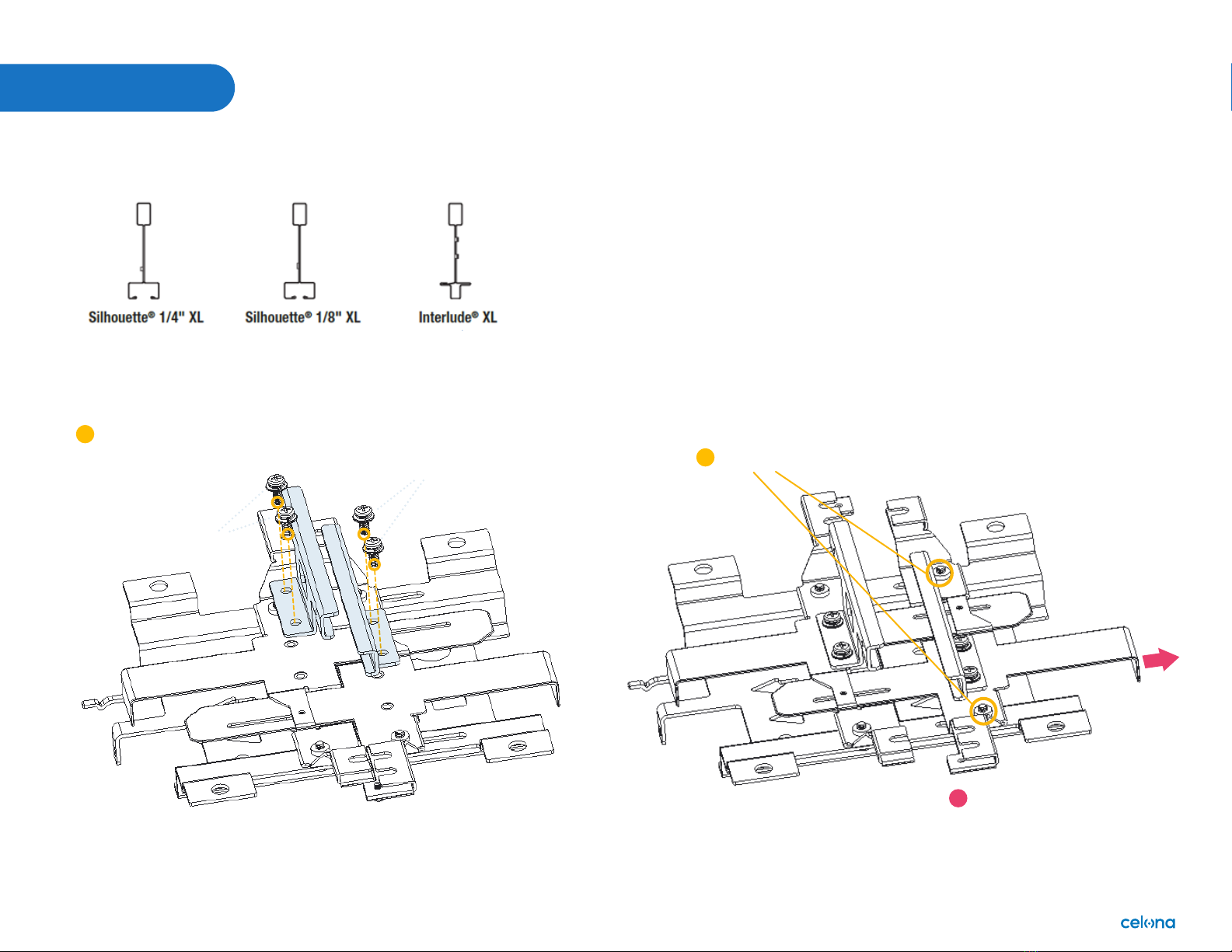
Step 4: Slide device to mounting kit, aligning the four screws and the slot.
Before slide the device
Slide device by arrow
direction to hold on
mounting kit.
1
M3*9 screw
1
Step 5: Fasten one M3*9 screw to fix device and mounting kit.
© Copyright 2023 Celona Inc. All rights reserved.
Installation Guide Celona Indoor Access Point AP 20 7
Mounting
Install on silhouette and interlude T-bar
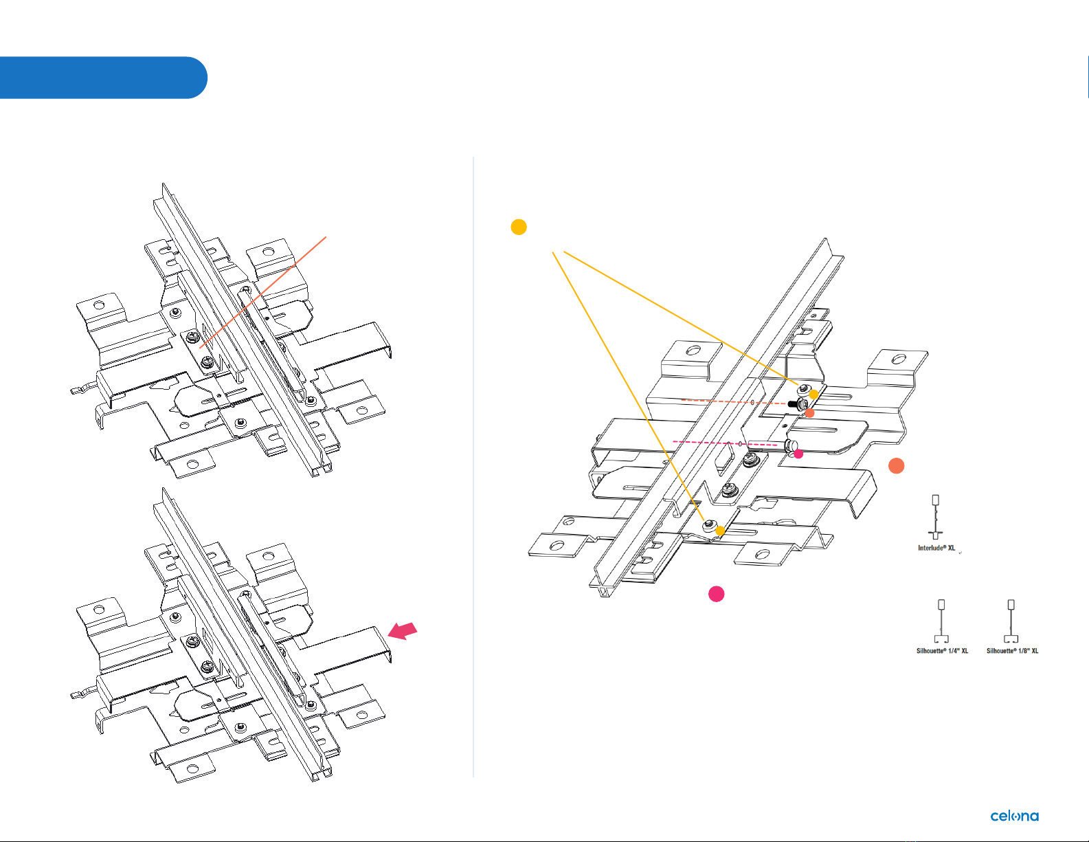
Step 1: Fix two bracket blocks onto the two grid brackets. Step 2: Loosen two screws and pull out the active grid bracket.
Loosen these two M4*10 screws
Pull out the active grid bracket
in the direction of the arrow
1
2
Fasten four screws to combine the two
bracket blocks on the grid bracket
1
Screws M4*10
Screws M4*10
© Copyright 2023 Celona Inc. All rights reserved.
Installation Guide Celona Indoor Access Point AP 20 8
Mounting
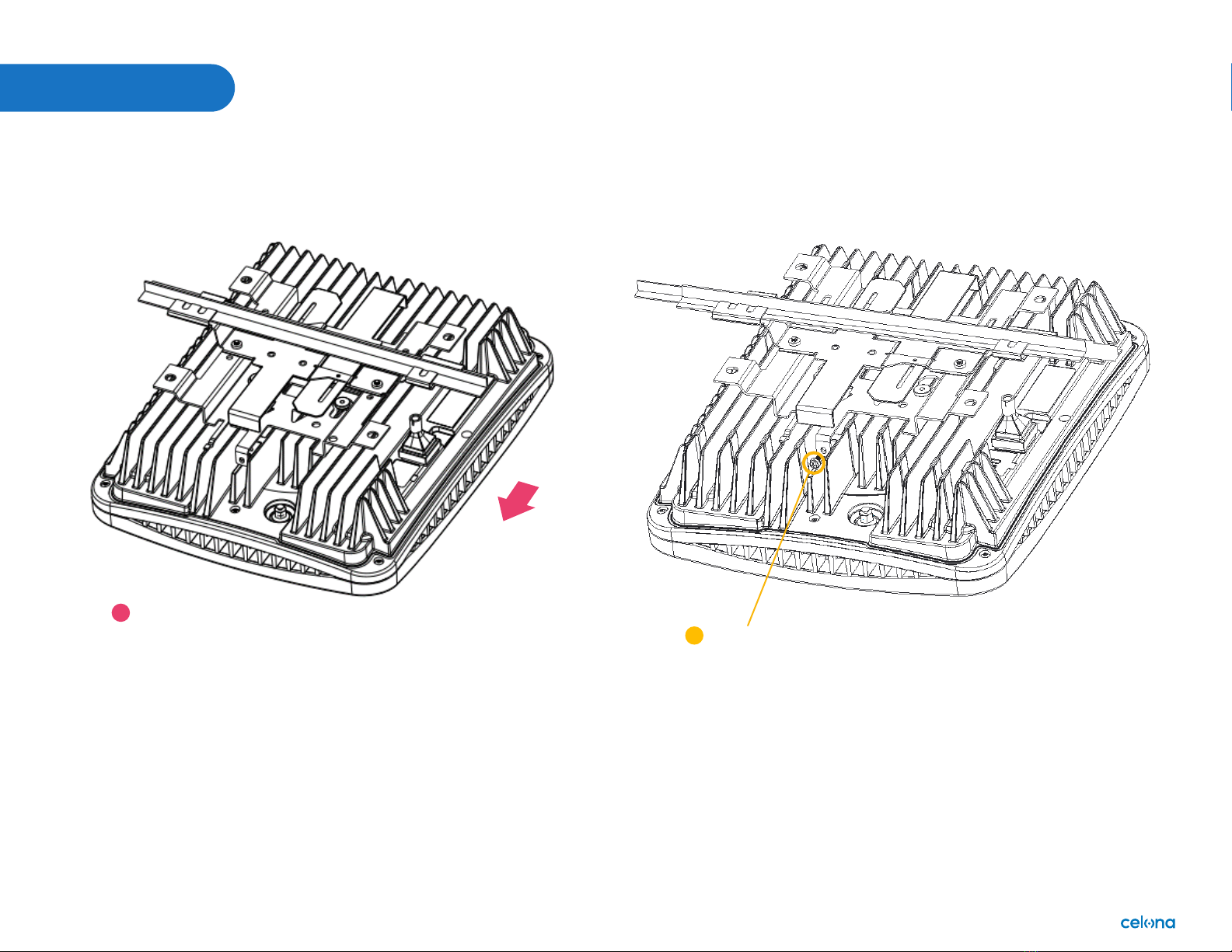
Step 3: Push the active grid bracket to the T-bar. Step 4: Fix the active grid bracket and fasten
two screw to prevent mounting kit from slipping
Fasten these two screws M4*10 to
secure the active grid bracket
Fasten one M3*9
or M3*6 screw.
1) Interlude’ XL T bar: use
screw M3*9;
2) Silhouette’ 1/4 and 1/8 XL
T bar: use screw M3*6.
Put the bracket block
on the fixed grid
bracket against one
side of the T-bar
Push the bracket block on
active grid bracket by arrow
direction to clamp another
side of T bar.
1
Fasten one screw M4*25.
2
3
1
1
2
3
© Copyright 2023 Celona Inc. All rights reserved.
Installation Guide Celona Indoor Access Point AP 20 9
Mounting
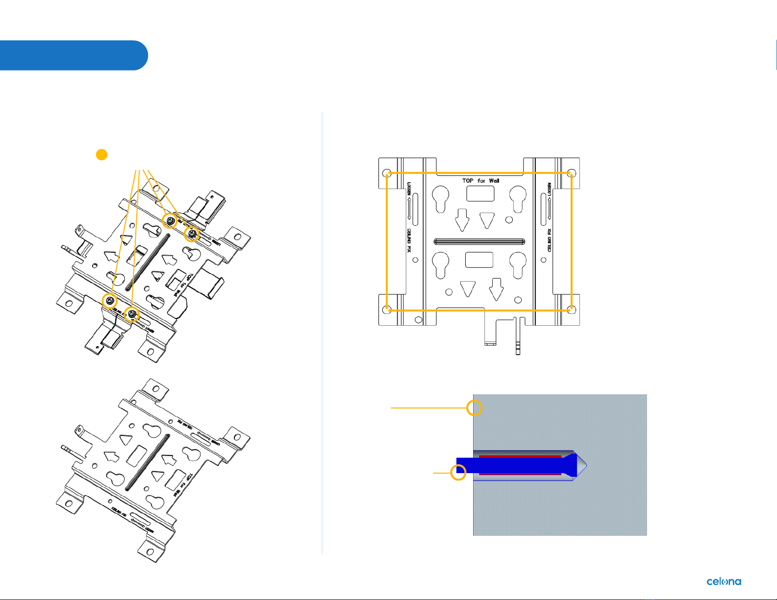
Step 5: Slide device to mounting kit, aligning the four screws and the slot.
Before slide the device
Step 6: Fasten one M3*9 screw to fix device and mounting kit.
Slide device by arrow
direction to hold on
mounting kit.
1
M3*9 screw
1
© Copyright 2023 Celona Inc. All rights reserved.
Installation Guide Celona Indoor Access Point AP 20 10
Install on a wall
Mounting
Step 1: Disassemble two grid brackets from
the mounting kit.
Step 2: Drill four holes on the wall using bit size Φ
8.00mm. See below of the distances.
Step 3: Insert the four expansion screws into holes.
Loosen these four M4*10 screws,
then remove the two grid brackets
Only the mounting kit will
be used for wall mounting
Hole distance: 167.20*124.00mm
Hole depth: 40.00mm
Wall
Expansion screw
1
124.00mm
167.20mm
Table des matières
Autres manuels Celona Point d'accès sans fil


Manuels Point d'accès sans fil populaires d'autres marques

D-Link
D-Link DWL-2100AP - AirPlus Xtreme G Manuel utilisateur

Ubiquiti
Ubiquiti NanoStation NSM2 Manuel utilisateur

Cisco
Cisco Aironet 1550 Series Manuel utilisateur

Aruba
Aruba IAP-335 Manuel utilisateur

Advantek Networks
Advantek Networks AWN-AP-54MR Manuel utilisateur

IP-COM
IP-COM AP355 Manuel utilisateur


