Cellar Cool CX Series Manuel utilisateur


Page 2 CC 090711
Copyright © 2011. CellarCool. All rights reserved.
is manual, the product design, and the design concepts are copyrighted by CellarCool, with all rights reserved. Your rights with
regard to the hardware and manual are subject to the restrictions and limitations imposed by the copyright laws of the United
States of America. Under copyright laws, this manual may not be copied, reproduced, translated, transmitted, or reduced to any
printed or electronic medium or to any machine-readable form, for any purpose, in whole or in part, without the written consent
of CellarCool.
Every eort has been made to ensure that the information in this manual is accurate. CellarCool is not responsible for printing or
clerical errors.
CellarCool reserves the right to make corrections or improvements to the information provided and to the related hardware at
any time, without notice.
CellarCool are registered trademarks, and ECE is a trademark of CellarCool. All rights reserved.
Mention of third-party products is for informational purposes only and constitutes neither an endorsement nor a recommenda-
tion. CellarCool assumes no liability with regard to the performance or use of these products.
09.07.10

Page 1
CellarCool Quick Reference Guide ........................................
Receiving & Inspecting e Unit ..........................................
Preparing the Wine Cellar ......................................................
Installation ................................................................................
Drainline ....................................................................................
System Operation ....................................................................
Maintenance Schedule ............................................................
Controller Features and Operation .......................................
Troubleshooting Guide ...........................................................
Technical Assistance ...............................................................
Installation Terms and Conditions ......................................
Technical Assistance ................................................................
2
3
4
6
10
11
11
12
13
15
16
17
TABLE OF CONTENTS
While great eort as been made to provide accurate guidelines, CellarCool cannot warrant its units to properly cool a particular enclosure. Customers are
cautioned that enclosure construction, unit location and many other factors can aect the operation and performance of the unit. erefore the suitability of the
unit for a specic enclosure or application must be determined by the customer and cannot be warranted by CellarCool
We manufacture, test and certify 100% of our wine cooling units in the USA. By
sourcing the best components and closely controlling our manufacturing processes,
we can assure the highest-quality, lowest defect manufacturing rates in the industry.

Front of unit
Back of unit
Page 2 CC 090711
SET
Drain Line
Screws in from bottom.
Outlet
Note: Upgraded units
have outlet in the back.
See page 6.
Posterior Grille
CellarCool QUICK REFERENCE GUIDE
ank you for purchasing a CellarCool cooling unit. We strive to provide the highest quality products and the best possible
customer service. If you have any questions about your CellarCool unit, please call us at 1(855) CELLAR-1.
is User’s Manual is intended to assist in the proper installation and maintenance of the CellarCool cooling system. In order
to ensure the longevity of your cooling unit, the equipment should be installed properly and have a proper care and mainte-
nance schedule. Please read and review this manual carefully and keep it for future reference.
What Is the CellarCool Cooling System?
e CellarCool system is a specialized refrigeration unit designed for one purpose only: to maintain the optimal temperature
and humidity levels conducive to the proper storage and aging of ne wines. It is a self-contained cooling unit designed to be
used as a forced-air through-the-wall unit. e CellarCool cooling system is especially designed for the use and application to
maintain optimal conditions for wine storage and aging. e system is fully self-contained and can be installed as a “ru-e-
Wall’ application. e standard “rough-the-Wall” units are temperature controlled via air sensor. e CellarCool unit can be
set at any temperature within the acceptable wine-aging range of 50°F to 67°F. It is designed to cool 30°F cooler than the ambi-
ent temperature of the space to which it is exhausting.
Air Sensing Probe
Controller
Front Grille

Page 3
Customer Warranty Registration
PLEASE COMPLETE AND RETURN THE WARRANTY CARD UPON RECEIPT OF THE UNIT TO ACTIVATE WARRANTY.
By completing the Product Registration Card, you will be conrmed in our customer database ensuring that your information is
on le to help you obtain ecient warranty service.
Please refer to pages 15-17 for complete terms and conditions, warranty guidelines, and policy for your CellarCool cooling unit.
Receiving and Inspecting the Unit
Note: CellarCool units are manufactured in the USA and tested prior to shipment.
• Li only at the designated hand hold locations on the shipping container or fully support the unit from underneath. A
shipment may include one or more boxes containing accessories.
• Before opening the container, inspect the packaging for any obvious signs of damage or mishandling.
Review the Packing Slip to Verify Contents
• Check the model number to ensure it is correct.
• Check that all factory options ordered are listed.
If any items listed on the packing slip do not match your order information, contact CellarCool Customer Service immediately
at 1(855) CELLAR-1.
Check the Accessory Kits for the following contents:
Kit One:
• CellarCool Owners User’s Manual
• Registration / Warranty Card
Kit Two:
• 6 - Screws, #6 x 3/4 Hex Washer Head
• 6 - Self Tapping Screws
• 1 - 10 . Drain Line tube, Plastic 3/8
• 1 - 4 1/2 . Insulation Foam
• 2 - Mounting Flanges
Please leave the CellarCool unit in its original box until you are ready for installation. is will allow you to move the product
safely without damaging it. When you are ready to remove the product from the box, refer to page 6-11 for installation
instructions.
Note: Save your box and all packaging materials. ey provide the only safe means of transporting/shipping the unit.
RECEIVING & INSPECTING THE UNIT
Model ____________________________________________ Serial Number _____________________________
Installed by ________________________________________________ Date _____________________________
CX C

Page 4 CC 090711
C' D A C
e performance and life of your CellarCool unit are contingent upon the steps you take in preparing the wine cellar.
Note: Improperly preparing your enclosure or incorrectly installing your CellarCool unit may cause unit failure, leaking of con-
densation, and other negative side eects.
IT IS HIGHLY RECOMMENDED THAT YOU OBTAIN THE ASSISTANCE OF A
WINE STORAGE PROFESSIONAL.
Wine storage professionals work with licensed contractors, refrigeration technicians, and racking companies to build well-
insulated, beautiful, and protective wine cellars. CellarCool has put together some useful tips to assist in the installation process.
Our recommendations are meant to act as a guide in the process of building a proper enclosure. Your intended location may
have specic needs that we do not address.
Wall & Ceiling Framing
Build wine cellar walls using standard 2x4 or 2x6 construction methods and ceiling joists following the guidelines of local and
state codes in your area. As a general rule, the thicker the walls and the higher the insulation factor in your cellar, the better it
will be at maintaining a consistent temperature.
Insulation
Insulation is REQUIRED with the use of the CellarCool product. Standard berglass or rigid foam insulation is normally used
in cellar construction or, in some cases, “blown-in” insulation is used. It is very important that all walls and ceilings are insu-
lated to keep the cellar temperature as consistent as possible during the summer and winter months. e R-factor, or quality of
insulation, is determined by the rate at which heat passes through the insulation. e higher the R-factor, the more resistant the
insulation is to conducting heat. Using higher R-values in insulation will lower your operating costs and unit run time. (R-13
minimum, R19 recommended, R30 for ceiling and exterior walls)
Mounting the Unit
e unit should be mounted within 18“ of the top of the room in order to achieve sucient cooling. As the room cools down,
the warm air will rise to the ceiling. Mounting the CellarCool high in the room will create a consistently cool environment by
capturing the warm air and replacing it with cool air. Mounting the unit low in the room will result in a temperature variation
in the room due to the unit’s inability to draw warm air from the ceiling of the cellar to the unit itself.
PREPARING THE WINE CELLAR
Cellar Wall
85ºF 55ºF
CellarCool
45°angled fans
(side view)
FRONT - WINE CELLARBACK - EXHAUST ROOM

Page 5
Ventilation
e necessity of dissipating heat away from the unit is critical to the unit’s performance and cannot be overstated. As the
unit operates and cools, a greater amount of heat is generated on the exhaust side of the unit. Adequate ventilation is required
in order to dissipate heat away from the unit. If ventilation is inadequate, the exhaust will heat up and adversely aect the unit’s
ability to cool.
Vapor Barrier
Vapor Barrier is REQUIRED to prevent the intrusion of water vapor so that the cellar can be kept at the correct temperature
and humidity. 6 mm plastic sheeting (recommended) should be applied to the warm side of the cellar walls. e vapor barrier
must also be applied to the outside walls and ceiling. If it is impossible to reach the outside, then the plastic must be applied
from within the cellar. e most common method is to wrap the entire interior, leaving the plastic loose in the stud cavity so
the insulation can be placed between each stud. All of the walls and ceiling must be wrapped in plastic for a complete vapor
barrier.
In areas of high humidity, such as Southern and Gulf States, the vapor barrier will prevent inltration of warm moist air. e
moist air can cause mold to form, and standing water in drain pans promote microbial and fungal growth that cause unpleasant
odors and indoor air quality problems. If mold is found, remove it immediately and sanitize that portion of the unit.
Unobstructed Airow
Unobstructed airow to and from the unit is a critical factor in the unit’s overall performance. Make sure there is a minimum 3 .
horizontal clearance from the rear of the unit as well as a minimum 3 . clearance in front of the evaporator fans. is will assure
that the unit can move the air around in an ecient manner. Avoid any attempt to camouage the unit by installing racking in
front of the unit. is will restrict the airow and lower the performance of the unit.
Ambient Temperature Factor
e cooling system has the ability to cool a maximum of 30°F below the ambient temperature of the room it is exhausting to.
erefore, you want to exhaust the unit in a room which will not exceed 85°F and preferably a consistent 75°F. Otherwise the
unit will not have the capacity to keep the wine at a desirable 55°F.
Door and Door Seal
At minimum an exterior grade (1 3/4”) door must be installed as a cellar door. It is very important that weather stripping is
attached to all 4 sides of the doorjamb. A bottom “sweep” or threshold is also required. e door must have a very good seal to
keep the cellar cool in and the warm air out. One of the most common problems with cooling units running continually is the
door not sealing properly.
Sizing the Unit to the Room
e specication chart will provide information on the units room size cooling capacity. ere are circumstances in which a
cellar design may require a larger unit due to some existing design restrictions. In such a case, we recommend that the customer
consider purchasing a unit with a larger capacity to compensate for the design limitations. Issues such as glass doors, concrete, or
brick walls and oors may seem adequate but do not oer the insulation capacity required to maintain the optimum environment.
cx4400 1000 81 7 14.25” x 19.75” x 21.63”
cx8800 2000 101 10 16.25” x 22” x 22.25”
cx3300 650 76 5 14.25” x 19.75” x 21.63”
Model Room Size Weight AMP’s Product Dimensions
(cubic feet) (lbs) (running) (W x H x D)
cx2200 350 55 314.25” x 13.25” x 16.38”
Temperature Delta - 30°F (when exhaust environment does not exceed above 85°F and below 50°F)
Warranty - 2 yr parts & labor / 5 yr compressor only
Page 6 CC 090711
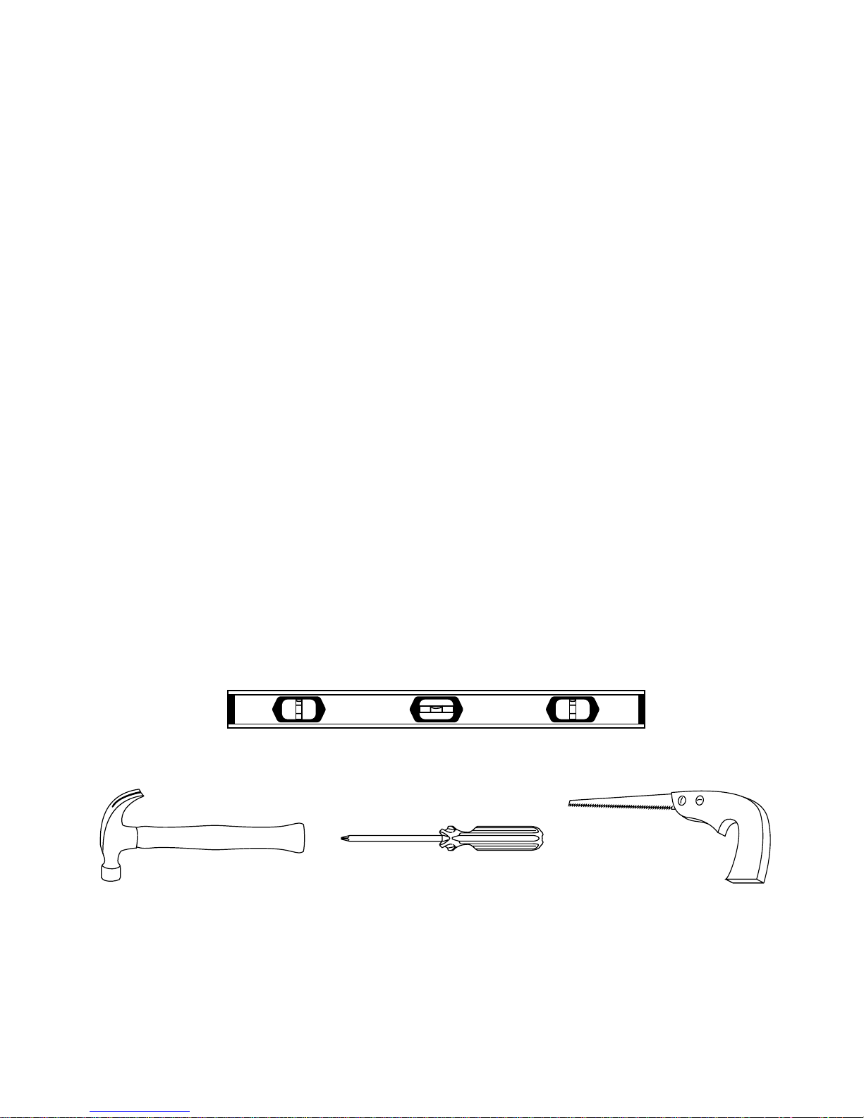
TOOLS NEEDED FOR CUTTING THE HOLE FOR THE CELLARCOOL UNIT
Hammer Saw
Screwdriver
Level
Electrical Needs
e CellarCool System requires a dedicated 110-volt 20-amp circuit. e unit draws a large amount of amps at initial start up.
By designating a dedicated circuit breaker, you will guarantee the unit has enough power to run eectively. Contact an electri-
cian for assistance with the installation of this dedicated electrical circuit:
1. Match the electrical outlet to the plug provided on the CellarCool unit.
2. Provide a dedicated circuit and wiring for the unit.
Electrical Outlet
e unit is equipped with a twelve foot power cord located on the evaporator/cellar side of the unit, which comes standard on
all units. An optional rear/outside cellar power cord can be requested at an additional charge. Plug your CellarCool unit into
a surge protector or power conditioner. As with any sensitive electrical equipment, the CellarCool electrical equipment may be
damaged by power surges and spikes. Power surges and spikes are not covered in the CellarCool warranty.
WE RECOMMEND THAT YOU DO NOT USE A GROUND FAULT INTERRUPTER (GFI) WITH THIS PRODUCT.
Testing Unit - Carefully remove your CellarCool unit from the box. Do not destroy your packaging material, as it
provides the only safe means of transporting the unit. Place the CellarCool system on a tabletop to prepare it for
installation and testing. Plug system into a live electrical outlet and turn unit on. e system may take up to 10 to
15 minutes before operating correctly, meaning all four fans are running. Cold air coming out on cellar side, hot
air coming out on exhaust side. Once the operation has been tested, turn the unit o, and unplug the unit from the
electrical outlet.*
* Note: If the system does not seem to be fully functional aer 15 minutes, please refer to the Troubleshooting Guide on page 13.
Units weigh 50-101 pounds and are cumbersome for one person to carry. We recommend that you get someone else to help
you during the installation process. NEVER LAY UNIT ON ITS SIDE.
INSTALLATION
TESTING UNIT BEFORE INSTALLATION
Page 7
SET
INSTALLATION cont.
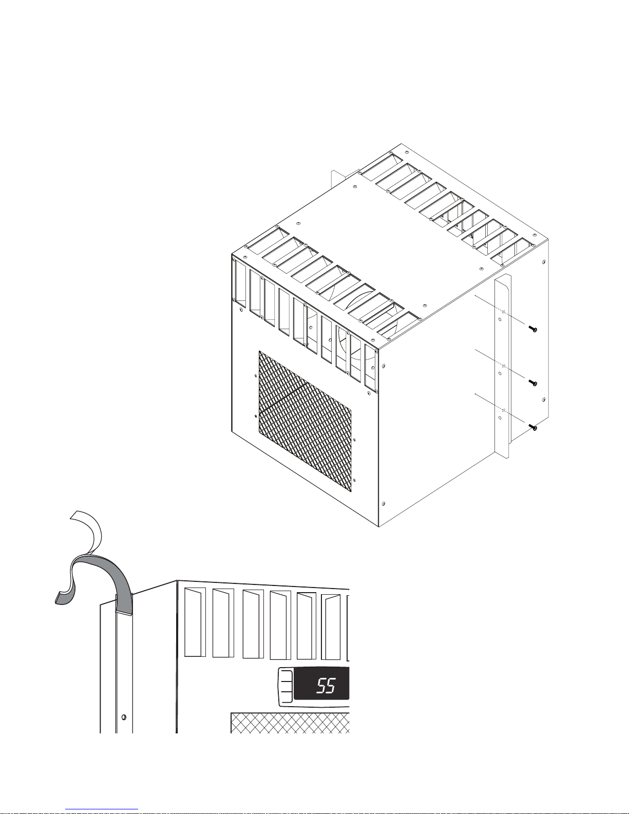
PREPARE UNIT FOR THROUGH-THE-WALL INSTALLATION
Mounting Flange Pieces
ere are two individual mounting ange located in Kit 2 of your enclosed accessory kits. ese ange pieces are designed to
be used on the backside of the CellarCool Series to mount to the exterior wall. ere are dimples located on the exterior of the
housing. e punch-outs are designed for specic through-the-wall installation mounts. Please refer to the illustration for loca-
tion of the punch-outs.
Applying Insulation Tape
Locate the four precut pieces of black foam
tape included with the system. Once you
have attached the ange pieces to the unit,
peel back the white-paper adhesive covering
and place on the edge of the brackets that
will be against the wall. is foam creates a
tight seal between the ange and the wall.
Back of unit
Front of unit

Page 8 CC 090711
STEP 2:
Using a saw, cut along the uppermost horizontal line until your saw reaches
the stud. Turn the saw around, inserting it into the cut you have just made, and
cut toward the opposite stud so that you have a clean horizontal cut between
the two studs. Be careful not to cut into the studs themselves. Now make the
second horizontal cut from stud to stud on the line below the rst cut.
Once the horizontal lines have been cut, make vertical cuts using the inside
edge of the studs as a guide. Once you have made both vertical cuts, you
should have a rectangular hole in the sheetrock. Now you have to make the
same hole on the other side of the wall. Repeat step 2 on the other side.
STEP 1:
Locate the center of the cellar. Using a stud nder, locate two
adjacent studs in the walls, and mark them with vertical lines.
Using a level and a pencil, mark a horizontal line on the wall
between the two studs, approximately 1.25 inches or as close as
possible if more than 1.25) from ceiling. Using a ruler to mea-
sure down (see chart) and mark another horizontal line parallel
to the rst one. e dimensions of the hole should be approxi-
mately 1/4 inch larger than the width and height of the unit.
INSTALLATION cont.
CUTTING THE HOLE FOR THE CELLARCOOL UNIT
Location of Supply and Return Grilles
Locate the supply and return grilles inside the cellar to create an airow pattern that maximizes air circulation in the room.
Avoid short circulation of the air.
DO NOT:
• Install through-the-wall return air grilles at oor level, as they will collect dust from the oor.
• Mount the unit lower than 18” from the top of the room.
• Locate the supply or return air grille where it is blocked by bottles, boxes or cases
Cut Hole Dimensions
cx2200 - 13.5" down
cx3300 - 20" down
cx4400 - 20" down
cx8800* - 22.25" down
*Note: Due to the size of the cx8800, modication
to wall framing will need to be made according to
local building codes.
Autres manuels pour CX Series
1
Table des matières
Autres manuels Cellar Cool Climatiseur

Cellar Cool
Cellar Cool 3500 Evaporator Manuel utilisateur

Cellar Cool
Cellar Cool WM 2500 Manuel utilisateur

Cellar Cool
Cellar Cool Ultimate Plus PFD3300 Manuel utilisateur

Cellar Cool
Cellar Cool 3500 Evaporator Manuel utilisateur

Cellar Cool
Cellar Cool Ultimate FM 8000 Manuel utilisateur

Cellar Cool
Cellar Cool CX Series Manuel utilisateur


