Celestica A2210 Manuel utilisateur

A2210
User’s Manual


A2210
User’sManual
SS030616-06
Celestica
9 Northeastern Boulevard
Salem, NH 03079

This User’s Manual is believed to contain accurate material at the time of printing. Celestica assumes no responsibility or liabilities
for any use of the information contained in the manual.
Celestica retains the right to make changes to any information included in this manual, without the need to notify other parties, or
to make changes in the product or manuals already distributed.
Celestica August 2003
All rights reserved.
ii

Table of Contents
Chapter 1 - INTRODUCTION
1.1 Overview 1-1
1.2 Feature Identification 1-3
1.3 Server Architecture 1-6
1.3.1 Main Board 1-6
1.3.2 Front Access Panel Board 1-6
1.3.3 Server Management Board 1-6
1.3.4 Dual-Channel SCSI Controller Board 1-6
1.3.5 Signal Interface Board 1-6
1.3.6 PCI-X Riser Board 1-7
1.4 External Connectivity 1-8
1.4.1 PS/2 Keyboard and Mouse Connector 1-8
1.4.2 Serial Port 1-8
1.4.3 USB Ports 1-8
1.4.4 External SCSI 1-9
1.4.5 Ethernet 1-9
1.5 Internal Connectivity 1-9
1.5.1 Mass Storage 1-9
1.6 Contacting Celestica 1-10
Chapter 2 - INSTALLATION
2.1 Unpacking the System 2-1
2.2 Before Powering On the System 2-2
2.2.1 Inspect the Server 2-2
2.2.2 Install Slide Rails 2-2
2.3 Powering On the System 2-4
Chapter 3 – SYSTEM INTERFACES
3.1 Switches/Buttons 3-1
3.2 Control Panel LEDs 3-2
Chapter 4 - SAFETY
4.1 General Precautions 4-1
4.2 Electrical Precautions 4-2
4.3 ESD Precautions 4-2
iii

4.4 Operating Precautions 4-3
Chapter 5 – MOTHERBOARD SET-UP
5.1 Adding/Replacing Dual Inline Memory Modules 5-1
5.1.1 Installation Procedure 5-1
5.1.2 Removal Procedure 5-2
5.2 Replacing the Processors and Heatsinks 5-2
5.3 Setting the Switches 5-5
5.4 Replacing the Motherboard 5-6
Chapter 6 – CHASSIS SET-UP
6.1 Replacing the Signal Interface Board 6-2
6.2 Replacing the Server Management Board 6-2
6.3 Replacing Dual-Channel SCSI Controller Board 6-3
6.4 Replacing the Front Access Panel Board 6-3
6.5 Replacing the PCI Riser Card 6-5
6.6 Replacing the PCI-X Cards 6-6
6.7 EIDE Cabling 6-9
6.7.1 Primary EIDE Cable 6-9
6.7.2 Secondary EIDE Cable 6-9
6.8 Replacing the IDE Disk Drives 6-10
6.8.1 Removing the IDE Drive Cage 6-10
6.8.2 Removing the SCSI Drive Cage 6-12
6.8.3 Removing the Drive from the Drive Cage 6-12
6.8.4 Removing the CD or DVD Drive 6-13
Chapter 7 - BIOS
7.1 BIOS Requirements 7-1
7.2 Clearing the CMOS BIOS 7-3
7.3 Flashing New BIOS 7-4
7.4 BIOS Screenshots 7-5
Appendix A - TECHNICAL SPECIFICATIONS
FCC Compliance Statement 1
Environmental Requirements 1
Operational Environment 1
Non-operational Environment 2
iv

Appendix B - CONNECTOR ASSIGNMENTS
External Connectors 3
VHDCI SCSI Connector 3
PS/2 Keyboard and Mouse Connector 5
Serial Port Connector 6
USB Connector 7
Internal Connectors 8
68-Pin SCSI Connector 8
SCSI SCA Connector 10
EIDE Port 11
64-Bit PCI Connectors 12
32-Bit PCI Connectors 15
v

vi

Chapter
1
USER’S MANUAL
1
Introduction
Overview and Features
T
his document provides guidance for setting up, configuring, and using the
A2210 server. This document also supplies general system operation
information.
1.1 Overview
The A2210 server is 1U platform based on AMD Opteron™ processors and
AMD HyperTransport chipsets. The feature sets are targeted for OEM and
system builder markets. Table 1 presents the primary hardware components
used on the A2210 platform.
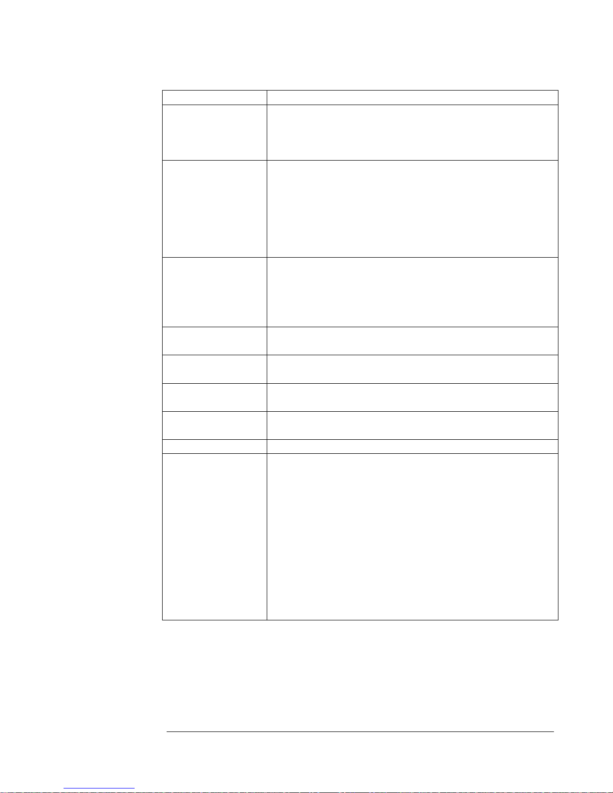
Table 1. Primary Hardware Components
Function Component
Processors AMD Opteron™ processors
•
•
Two processors each with three 16x16 HyperTransport
links
DDR memory controller and bus interface
Memory •
•
Processor H0 - four DDR DIMM slots with a maximum
of 16 Gbytes registered DDR using 1 Gbit x 4 bank
technology
Processor H1 - four DDR DIMM slots with a maximum
of 16 Gbytes registered DDR using 1 Gbit x 4 bank
technology
1-1
USER’S MANUAL
Function Component
PCI-X Tunnel AMD-8131. HyperTransport PCI-X Tunnel
•
•
•
One 16x16 HyperTransport I/O bus interface
One 8x8 HyperTransport I/O bus interface
Two PCI-X bridges and bus interfaces
Peripheral Bus
Controller AMD-8111. HyperTransport I/O Hub
•
•
•
•
•
One 8x8 HyperTransport I/O bus interface
Two USB ports controlled by the peripheral bus
controller
LPC Interface for ROM and Super I/O
Two UDMA133 EIDE ports
One 33-MHz, 32-bit PCI slot
LPC Super I/O Winbond W83627HF Super I/O
•
•
•
•
One Floppy connector
One 16550-compatible serial port
Two PS/2 ports for keyboard and mouse
One hardware monitor
SCSI Controller LSI 53C1030
•Dual-Channel, Ultra320 capable
Gigabit Ethernet
Controller Broadcom BCM5704
•Dual 10/100/1000 ports
Server
Management Qlogic Zircon UL Baseboard Management Controller
•IPMI 1.5 compliant
Optional Video ATI Rage XL graphics controller with 4 Mbytes of
memory via a small form factor PCI card
Clock Generator •TI A-PCDC960 or ICS 950401AF
Miscellaneous •
•
•
•
•
•
•
•
•
•
Miscellaneous debug and test features
Main Board
oTwelve layers
oE-ATX form factor
Custom 500W power supply
PC2001 Compliant
WHQL Compliant
Energy Star Compliant
WFM 2.0 Compliant (Wired for Management)
PCI-X 1.0 and PCI 2.2 Compliant
USB 1.1 (OHCI) Compliant
ACPI 1.0b Compliant
1-2
Table des matières


