Carmanah F Series Manuel utilisateur
Page 1
F Series
APPLIED INFORMATION (AI) INTEGRATION INSTALL GUIDE
Carmanah Technologies Corp. | 250 Bay St, Victoria, BC V9A 3K5, Canada | 1.250.380.0052 | customerservice@carmanah.com | carmanah.com
89104_InstallGuide_TRA_F-Series_AI_Integration_Kit_RevA
Page 2
F Series
APPLIED INFORMATION (AI) INTEGRATION INSTALL GUIDE
Carmanah Technologies Corp. | 250 Bay St, Victoria, BC V9A 3K5, Canada | 1.250.380.0052 | customerservice@carmanah.com | carmanah.com
1.0 Warnings and Precautions
The following symbols indicate important safety warnings and precautions throughout this manual:
1.1 Warranty Disclaimer
This manual will familiarize you with the features, operation standards, and installation of Carmanah’s F Series Applied Information (AI) system.
Failure to comply with the use, storage, maintenance, installation or placement instructions detailed in this manual could void the warranty.
1.2 Standards
Perform all installation, wiring, grounding and maintenance in conformance with local building and electrical codes. Adherence to the National
Electrical Code (NEC) is mandatory to comply with any certification markings. Non-adherence to code may void the warranty.
WARNING indicates that serious bodily harm or death may result from failure to adhere to the precautions.
CAUTION indicates that damage to equipment may result if the instructions are not followed.
NOTE suggests optimal conditions and provides additional information.
Page 3
F Series
APPLIED INFORMATION (AI) INTEGRATION INSTALL GUIDE
Carmanah Technologies Corp. | 250 Bay St, Victoria, BC V9A 3K5, Canada | 1.250.380.0052 | customerservice@carmanah.com | carmanah.com
1.3 Safety and Usage Precautions
Batteries are shipped fully charged. Use extreme caution when handling the batteries as they can generate
hazardous short-circuit currents. Remove all jewelry (bracelets, metal-strap watches, etc.) before handling
the batteries.
Solar panels produce DC electricity when exposed to light and can therefore produce an electrical shock or
burn. To render solar panels inoperative, remove them from sunlight or fully cover their front surface with an
opaque material.
Before lifting any heavy or bulky equipment, ensure the load is secured so moving parts do not shift, and that
it can be lifted as far as needed without back strain or loss of grip. Installation may require more than one
person.
Ensure the equipment is not powered during installation and wiring of the system.
Recheck all completed wiring for proper polarity prior to energizing the system.
Changes or modifications to Carmanah equipment not expressly approved by Carmanah could void both the
user's authority to operate the equipment and the warranty.
Page 4
F Series
APPLIED INFORMATION (AI) INTEGRATION INSTALL GUIDE
Carmanah Technologies Corp. | 250 Bay St, Victoria, BC V9A 3K5, Canada | 1.250.380.0052 | customerservice@carmanah.com | carmanah.com
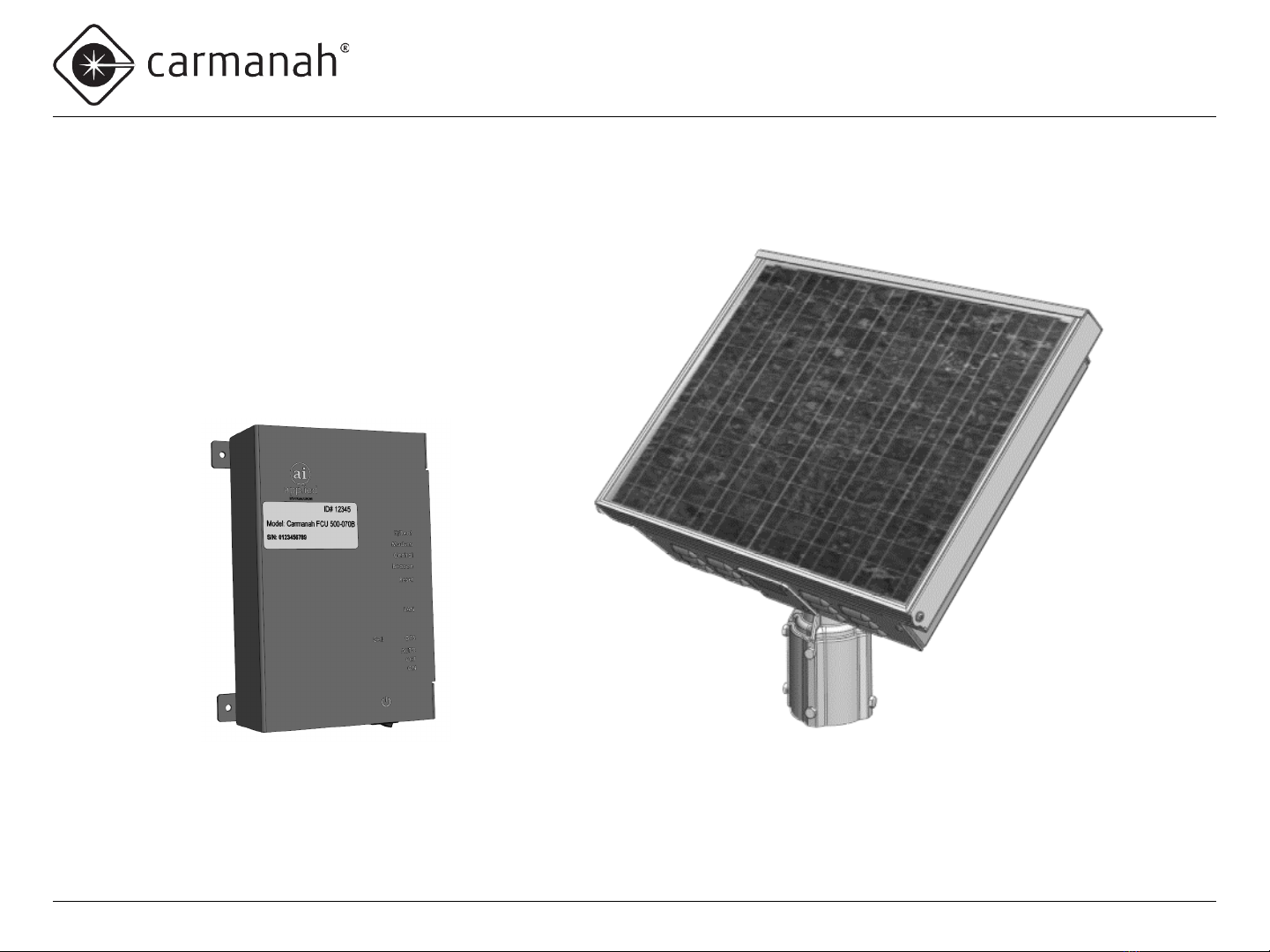
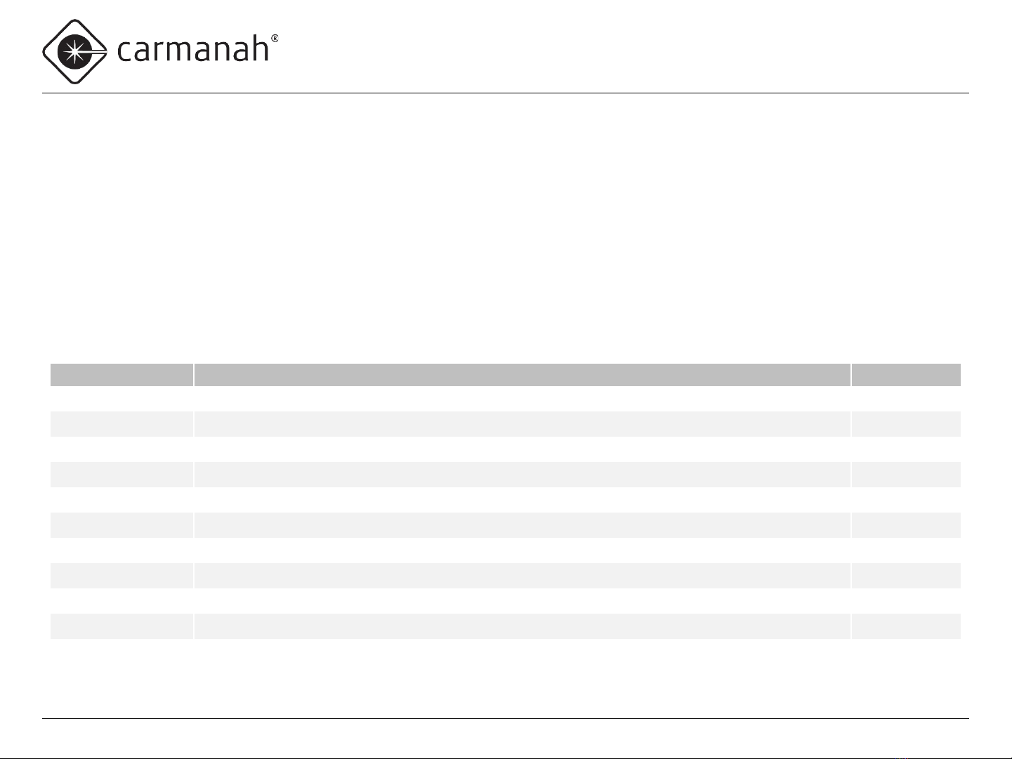
1.5 System Components
The F Series AI Integration Kit consists of the following items:
Carmanah Part # Description Quantity
80992 Bracket, Mount, Time Clock, XAV or Relay, 30W F-Series 1
50548 Screw, Machine, #8-32 x 3/8" Phillips Pan, SS 4
83093 Harness, AI 16-pin Connector to TB 1
87917 Adapter, 90°, SMA Plug Male Pin to SMA Jack Female Socket 2
84703 Wago 221-413 3-position Splice Terminal 2
84705 Wago 221-415 5-position Splice Terminal 2
54246 Cable Tie, 4 Inch 2
84708 Wire, Hookup, 16AWG Red 6 Inch
84709 Wire, Hookup, 16AWG Black 3 Inch
89106 Heat Shrink Tubing, 3/8" ID, 2:1, Glue-Lined, black 1 Inch
89104 Install Guide, AI Integration Kit, F-Series 1
1.4 Applications
For Carmanah R829-F and R247-F systems, the F Series AI Integration Kit allows for remote system monitoring, scheduling and control. With
Carmanah R820-F and R920-F Rectangular Rapid Flashing Beacon (RRFB) systems, the F Series AI Integration Kit allows remote system
monitoring.

Page 5
F Series
APPLIED INFORMATION (AI) INTEGRATION INSTALL GUIDE
Carmanah Technologies Corp. | 250 Bay St, Victoria, BC V9A 3K5, Canada | 1.250.380.0052 | customerservice@carmanah.com | carmanah.com
2.0 Tools and Materials Required
The following tools and materials may be required to install the AI Integration Kit into your F Series system:
•Drill and ½” drill bit
• Deburring tool or similar
•Crescent wrench
•Side cutters
•Heat gun
•3/32” flat blade screwdriver
•Multi-bit screwdriver
•Electrical multimeter
Page 6
F Series
APPLIED INFORMATION (AI) INTEGRATION INSTALL GUIDE
Carmanah Technologies Corp. | 250 Bay St, Victoria, BC V9A 3K5, Canada | 1.250.380.0052 | customerservice@carmanah.com | carmanah.com
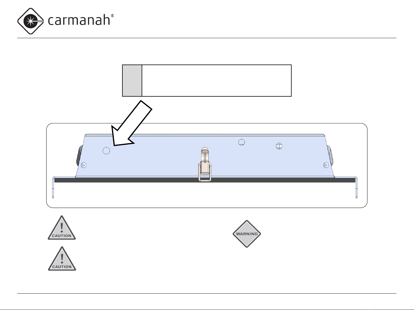
Drill Hole for Antenna
1
•Use the indentation to locate the tip of the drill bit.
•Drill a ½” hole on top of the enclosure.
•Deburr hole and remove all aluminum chips.
Ensure equipment is not powered
during installation and wiring of
the system. Recheck all completed
wiring for proper polarity prior to
energizing the system.
Ensure all metal chips are removed
to prevent system damage caused
by short circuits.
Ensure that no burrs are present
that would interfere with the
antenna seal.
Page 7
F Series
APPLIED INFORMATION (AI) INTEGRATION INSTALL GUIDE
Carmanah Technologies Corp. | 250 Bay St, Victoria, BC V9A 3K5, Canada | 1.250.380.0052 | customerservice@carmanah.com | carmanah.com
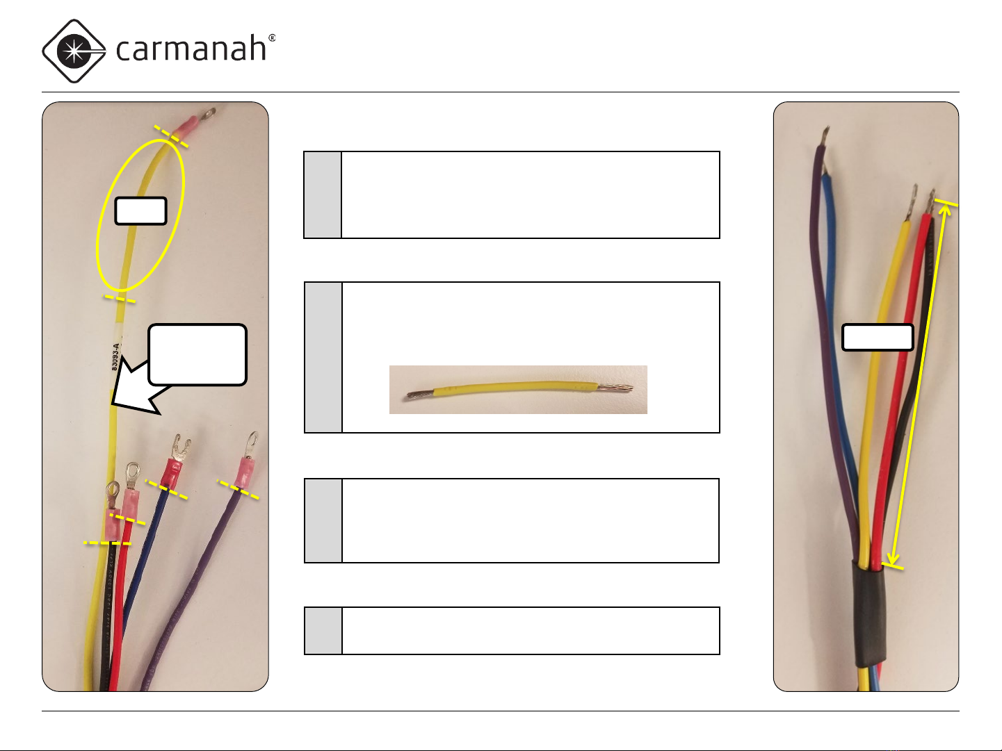
Prepare AI Harness
2
•Obtain AI harness.
•Cut and remove terminals of the five wires shown
(violet, blue, black, red and yellow).
•Leave green wire ring terminal intact (not shown).
4
•Install provided heat-shrink tubing around the five wires
4.25” from end of black wire (other wires will end up
being longer).
•Use heat gun to affix the heat shrink tubing.
5•Strip insulation of the five wires 0.35”.
3
•Cut yellow wire to same length as black wire.
•Cut a three-inch section of yellow wire and strip each
end 0.35”, for use later.
3”
Discard
leftover
wire
4.25”
Page 8
F Series
APPLIED INFORMATION (AI) INTEGRATION INSTALL GUIDE
Carmanah Technologies Corp. | 250 Bay St, Victoria, BC V9A 3K5, Canada | 1.250.380.0052 | customerservice@carmanah.com | carmanah.com
Remove EMS Screws
If radio is present, ensure radio pins are not bent and antenna cable is not damaged.
6
•Unlatch and swing the solar panel open.
•Remove the four EMS cover screws.
•Swing the EMS down to access the
internal wiring.
Page 9
F Series
APPLIED INFORMATION (AI) INTEGRATION INSTALL GUIDE
Carmanah Technologies Corp. | 250 Bay St, Victoria, BC V9A 3K5, Canada | 1.250.380.0052 | customerservice@carmanah.com | carmanah.com
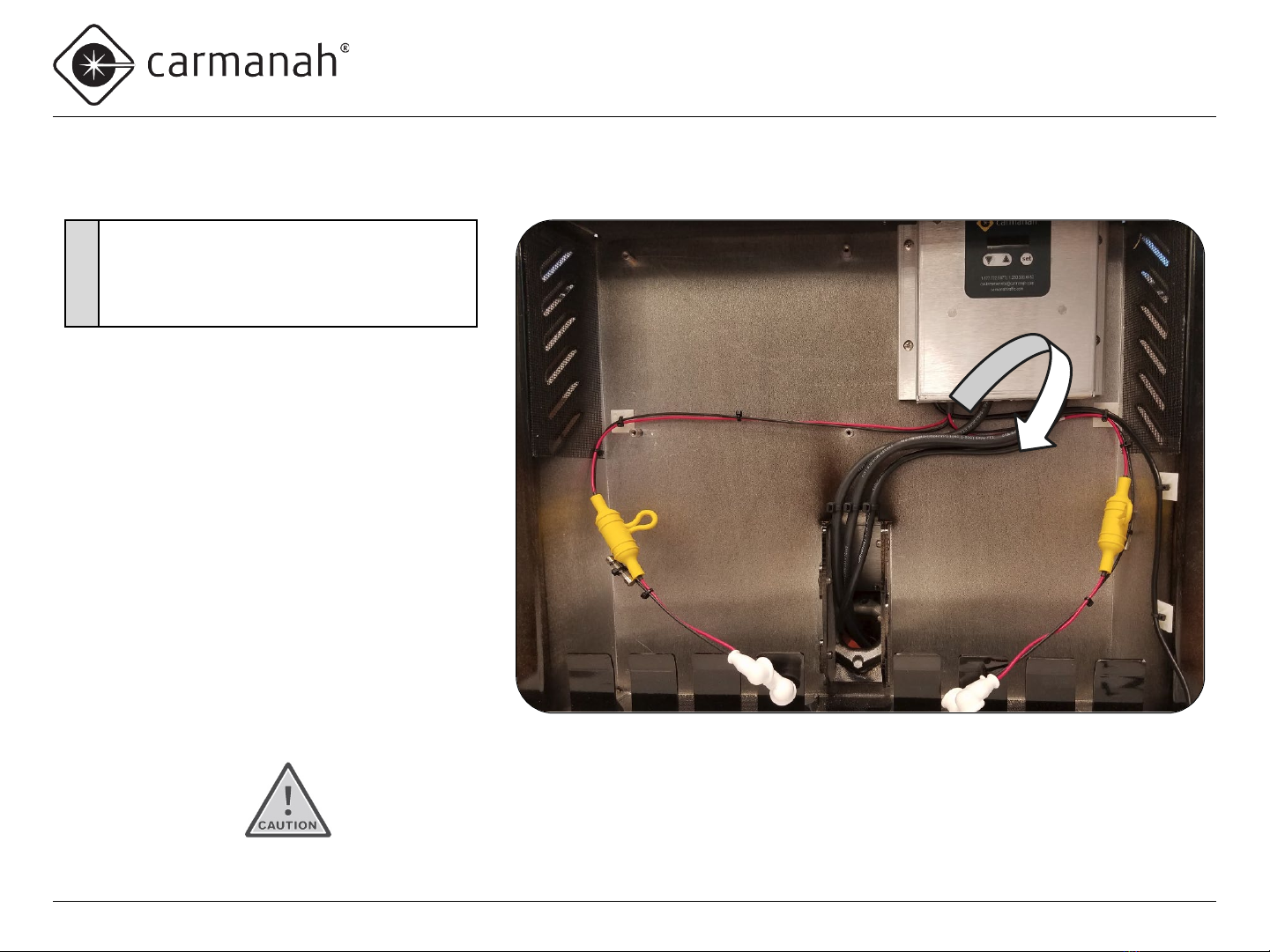
Remove Battery Harness Wires from Circuit Board (EMS)
7•Remove battery harness wires from battery circuit board terminal by pushing down on
each terminal button with small flat bladed screwdriver and pulling out each wire.
Page 10
F Series
APPLIED INFORMATION (AI) INTEGRATION INSTALL GUIDE
Carmanah Technologies Corp. | 250 Bay St, Victoria, BC V9A 3K5, Canada | 1.250.380.0052 | customerservice@carmanah.com | carmanah.com
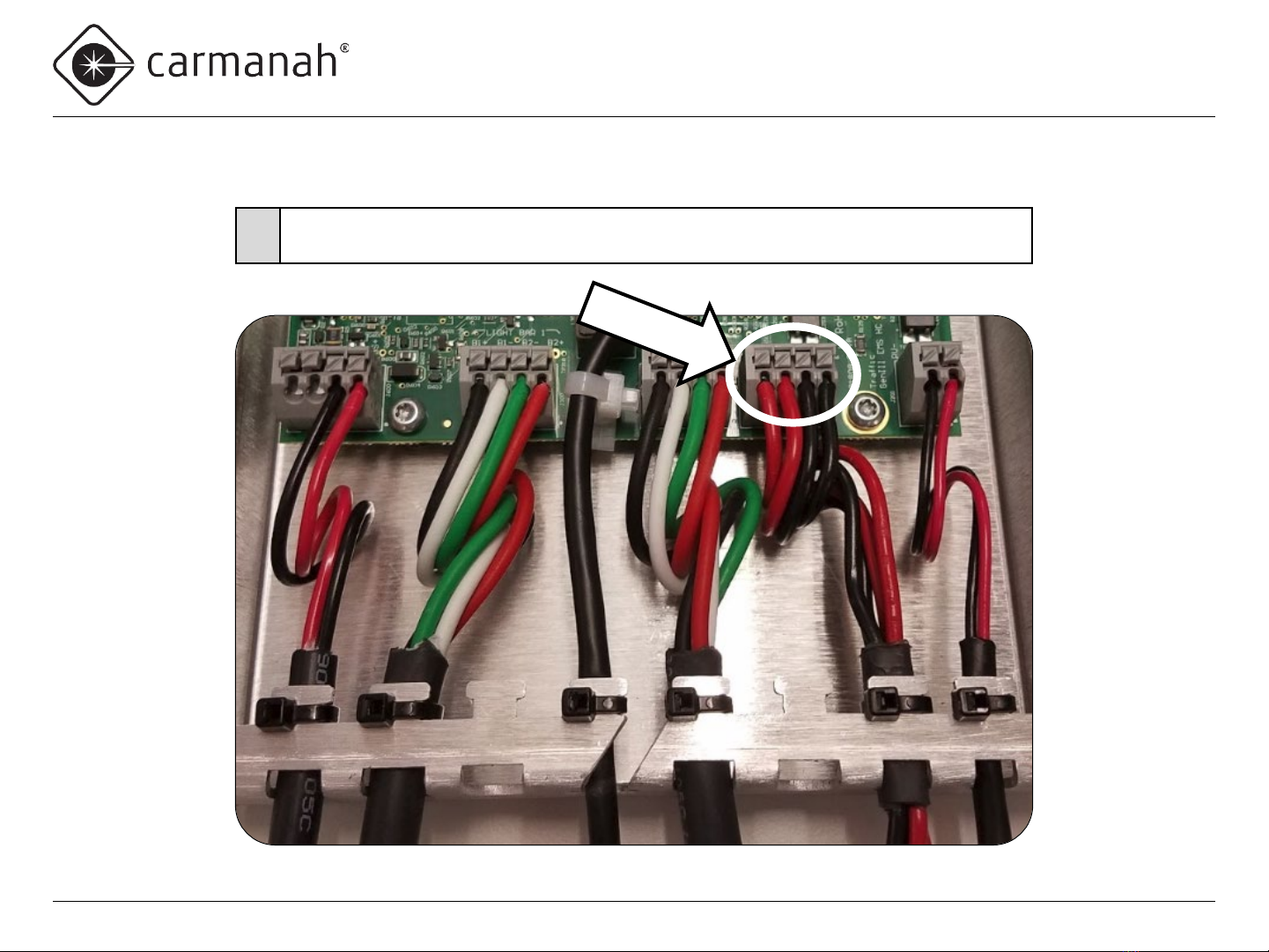
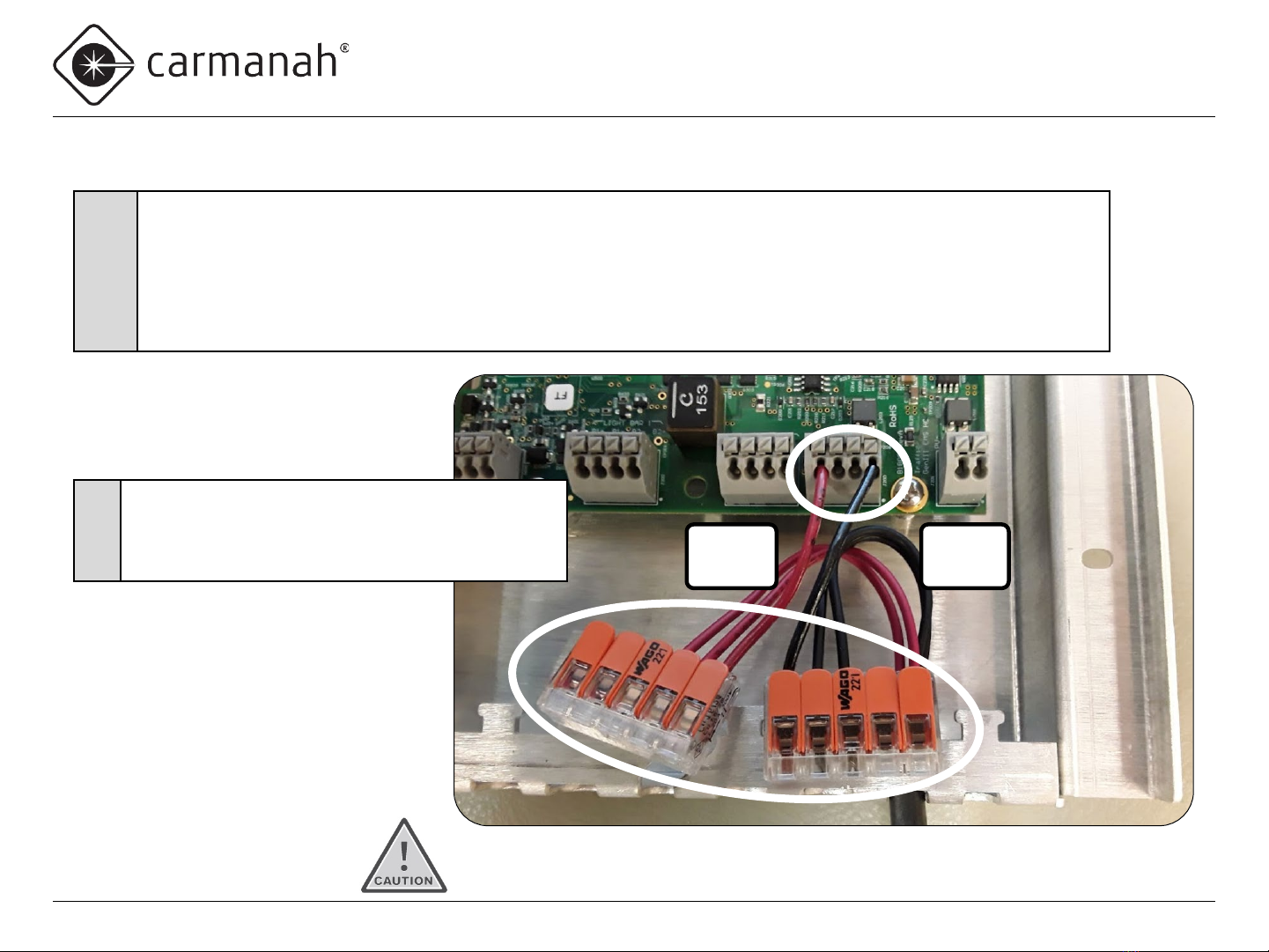
Install Battery Jumper Wires and Splice Terminals
Red
wires
Black
wires
8
•Obtain 3” of red and 3” of black wire supplied with the kit.
•Strip ends of both wires 0.35”.
•Use small flat bladed screwdriver to depress each terminal button and insert the wire into the terminal.
•Install one end of the red wire into the left BAT+ terminal.
•Install one end of the black wire into the right BAT− terminal.
•Insert the other end of each wire into two of the 5-position splice terminals.
Make sure all wire strands go into the terminal hole.
9
•Route the two red battery harness wires into the
splice terminal with the red wire from BAT+.
•Route the two black battery harness wires into the
splice terminal with the black wire from BAT−.
Ce manuel convient aux modèles suivants
2
Table des matières
Autres manuels Carmanah Onduleur


