Cardio Theater On-LineWireless Digital Transmitter Guide rapide
On-Line
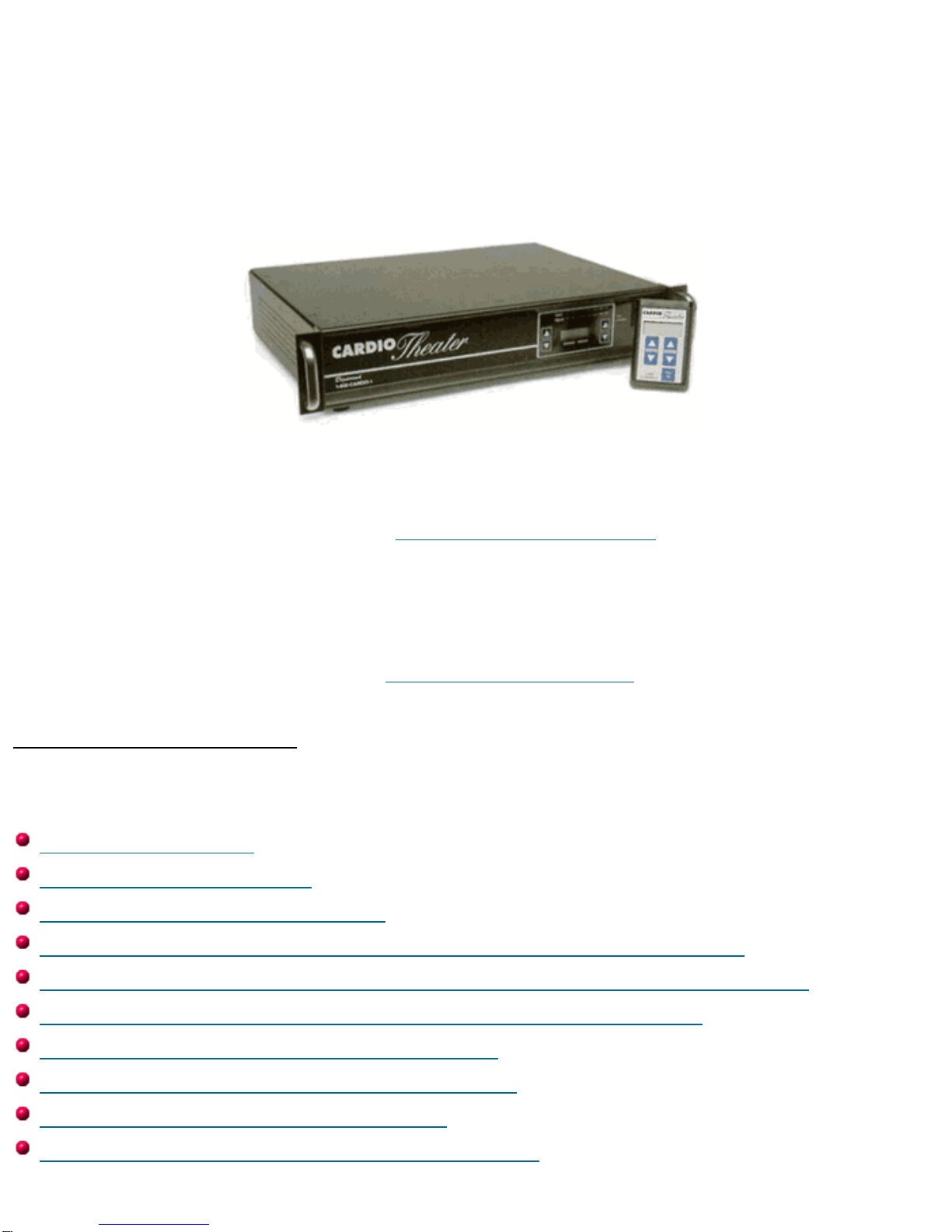
Cardio Theater Wireless Digital Transmitter
Installation and Instruction Manual
Full installation instructions accompany your Cardio Theater equipment order. This On-Line version of our
Installation/Instruction Manual is included in our web site for your convenience. If you have any questions
regarding your installation that are not covered by this Manual or by our Troubleshooting Guide, please
contact our Technical Support Department:
Cardio Theater Inc.
Service Department
Toll-Free Telephone in the United States: 1-800-776-6695
International Telephone, dial code for United States, then: (425) 486-9292
E-mail: [email protected]
Table of Contents
(Click to jump to the page you want to see.)
Before you begin
Important Safeguards
Suggestions for Installation
Installation: Controls and Indicators - Digital Transmitter
Installation: Controls and Indicators - Monitors and Receivers
Installation: System Connections: Digital Transmitter
Installation: Receiver Configurations
Installation: Attaching Upper Monitors
Installation: Attaching Receivers
Setup and Operation: Transmitter Setup
Specifications
Before You Begin
Please insure that you have all of the required equipment before disposing of any
packing materials.
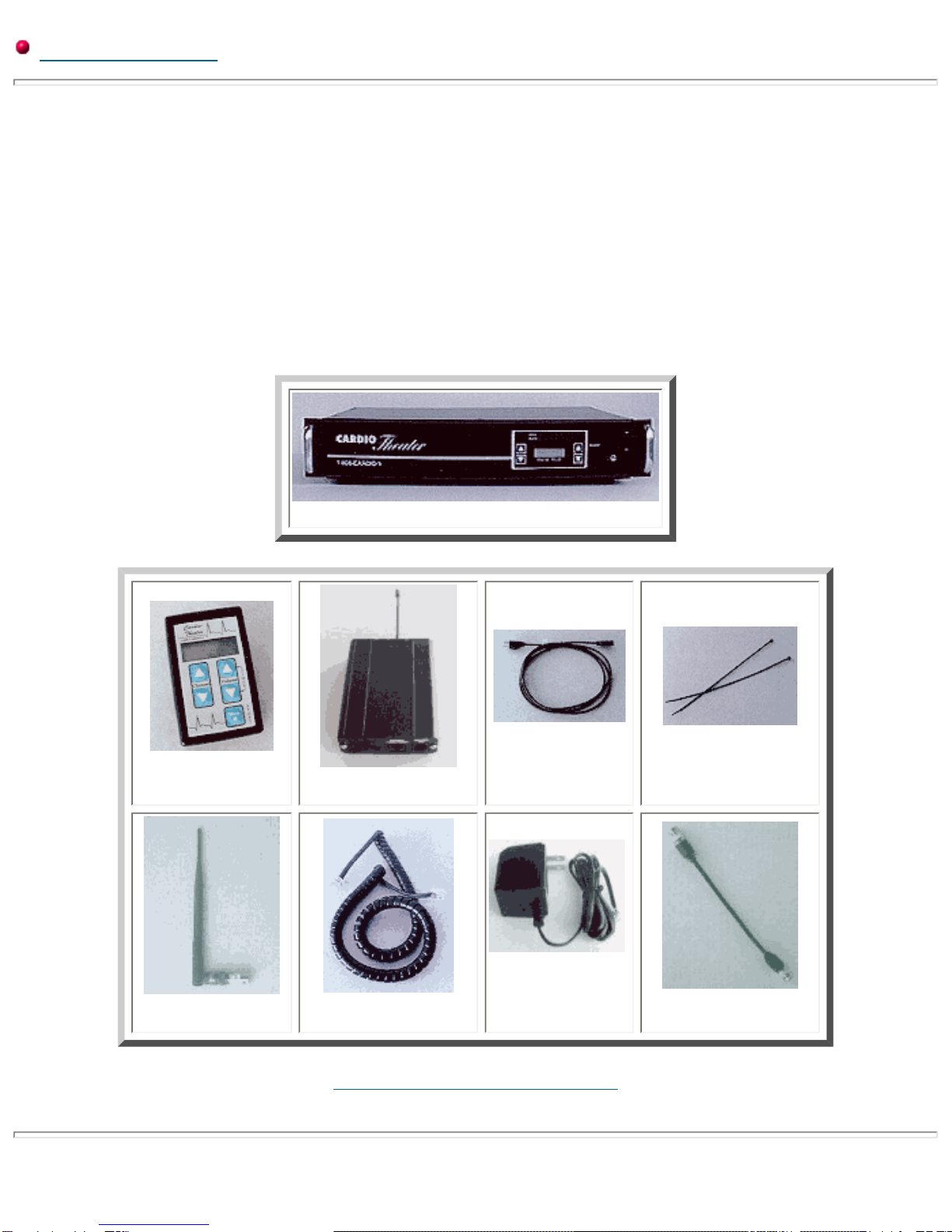
Equipment List:
Wireless Digital Transmitter
Upper Monitors,
quantity as ordered Receivers,
quantity as ordered
Power Cord,
quantity (1) Plastic wire ties;
(4) for each Upper Monitor
Antenna,
(1) for each Transmitter Coiled Cables;
(1) for each Upper Monitor
Power Adapter;
As ordered Coax Cable;
(1) for each Floor Monitor
Click here to go back to the Index.
Important Safeguards
Please read all of these safeguards before operating the unit. Follow all warnings placed on the unit and adhere to the
operating and use instructions. Retain your manual for future reference.
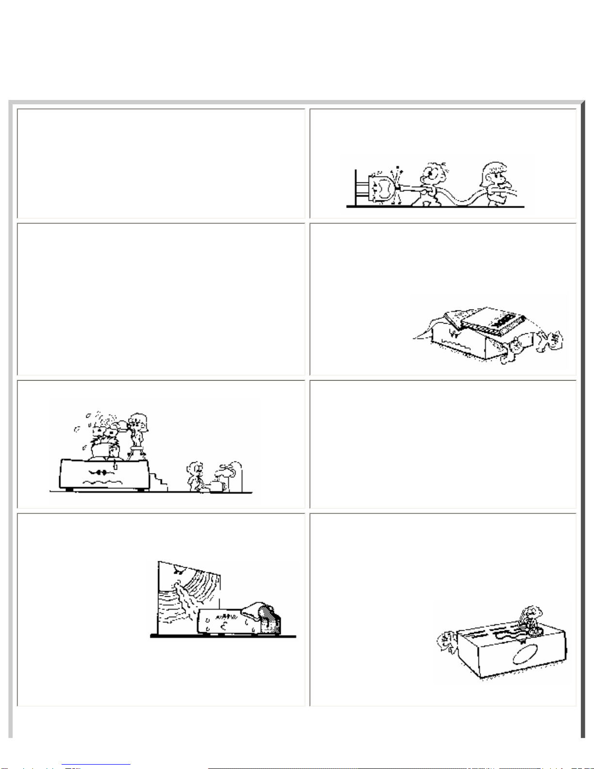
1. Power sources - Connect the unit to a power source only
of the type described in the operating instructions or as marked
on the appliance.
2. Power cord protection - Route all power-supply
cords so that they are not walked on or pinched by items
placed upon or against
them.
3. Grounding - Take precautions so that the grounding or
polarization means of the unit are not defeated. 4. Ventilation - Position the unit so that its location does
not interfere with ventilation. To maintain good
ventilation, do not put items on or over the unit. Do not
use the unit on a cushioned surface that may block the
ventilation openings.
5. Water and moisture - Do not locate the unit near
water. 6. Temperature - The unit may not function properly if
used at extreme temperatures. The ideal temperature is
41oF (5oC) to 87oF (30oC)
7. Heat - The unit should be located away from heat sources
such as radiators, heat registers, stoves, etc 8. Electric shock - Care should be taken so that objects
do not fall and liquid is not spilled on the enclosure. If a
metal object, such as a hairpin or a needle, comes in
contact with the inside of this unit, a dangerous electric
shock may result.
9. Enclosure removal - Never open the enclosure. If the
internal parts are accidentally touched, a serious shock may
occur.
10. Cleaning - Do not use solvents such as alcohol;
paint thinner, etc. to clean the unit. Use a clean dry cloth.
11. Abnormal smell - If an abnormal smell is detected,
immediately turn the power OFF and disconnect the power
cord. Contact your dealer or service center.
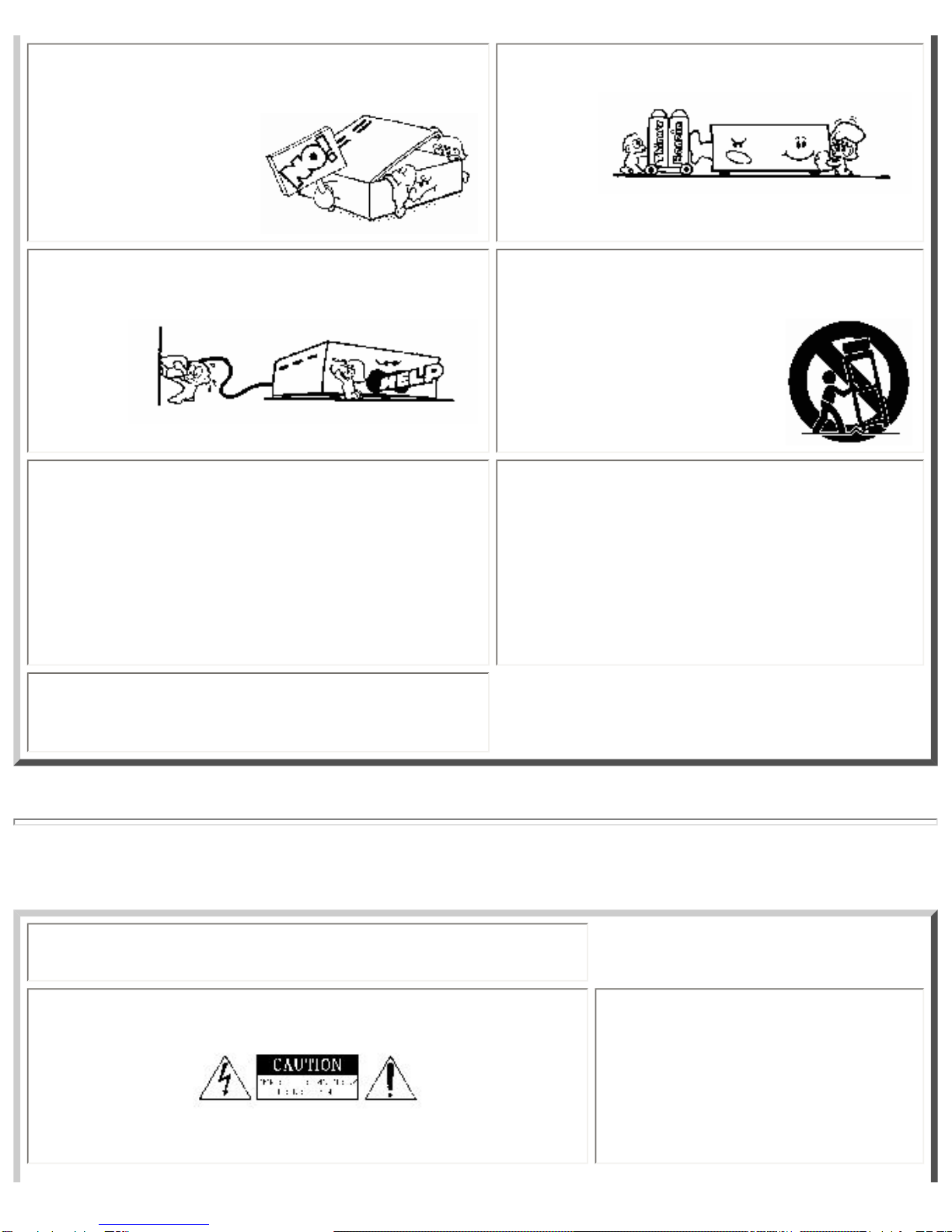
12. Stands - Any component should be moved with
care. Quick or excessive force could cause the stand to
overturn.
13. Nonuse periods - The power cord should be
disconnected when left unused for a long period of time.
14. Damage requiring service - The unit should be
serviced by a qualified technician when:
A. The power supply cord or the plug has been damaged;
B. Objects have fallen, or liquid has been spilled into the
unit;
C. The unit has been exposed to rain;
D. The unit does not appear to operate normally or
exhibits a marked change in performance; or
E. The unit has been dropped, or the enclosure damaged.
15. Servicing - The user should not attempt to service the
unit beyond that described in this manual. All other servicing
should be referred to a qualified technician.
Safety Precautions
WARNING: To prevent fire or electric shock, do not expose this appliance
to rain or moisture.
Caution: If you see this symbol, be
aware of its meaning: To reduce the
risk of electric shock, do not remove
the cover or back of the unit. No
user-serviceable parts are inside.
Refer servicing to a qualified
technician.
This symbol is intended to alert the
user to the presence of uninsulated
"dangerous voltage" within the
product's enclosure that may be of
sufficient magnitude to constitute a
risk of electric shock to persons.
This symbol is intended to alert the
user to the presence of important
operating and maintenance
instructions in the literature
accompanying the unit.
Click here to go back to the Index.
Suggestions for Installation
General Suggestions
❍Group the audio components in a single location to minimize cabling. Always place the Transmitter directly on top
of amp when stacking with the other audio components.
❍If the audio components are stacked in a stereo cabinet, insure that there is adequate ventilation. The Cardio
Theater Amplifier and Digital Transmitter each require a minimum one inch (1") clearance on both sides for
ventilation.
Transmitter:
❍Place the Digital Transmitter in a well ventilated area with the front and back easily accessible.
❍Place the transmitter as high as possible to obtain the best possible transmission range.
❍Make sure the antenna on back of transmitter is in the vertical position.
Upper Monitors:
❍When mounting Upper Monitors to equipment, take care not to interfere with the normal operation of the
equipment.
❍Likewise, the power connections and the coiled cable connecting the Receiver box to the Upper Monitor should not
interfere with normal operation of the cardiovascular equipment.

❍If mounting the Upper Monitor to a control panel, avoid covering controls or indicators.
Receivers:
❍The Receivers should be mounted as high as possible on the cardiovascular equipment.
❍Mount the Receivers so that the antenna is on top in the vertical position.
❍Mount the Receivers securely so that vibration from normal equipment operation does not cause the receiver to
move.
Click here to go back to the Index.
Controls and Indicators
Digital Transmitter - Front
Legend for Digital Transmitter - Front
1. Channel select
For setting desired channel to be adjusted.
2. Channel Indicator
Indicates current channel.
3. Frequency Indicator
Indicates frequency assignment.
4. Frequency Select
For setting the frequency assignment.
5. Power-on Indicator
Lights when main power switch is on.
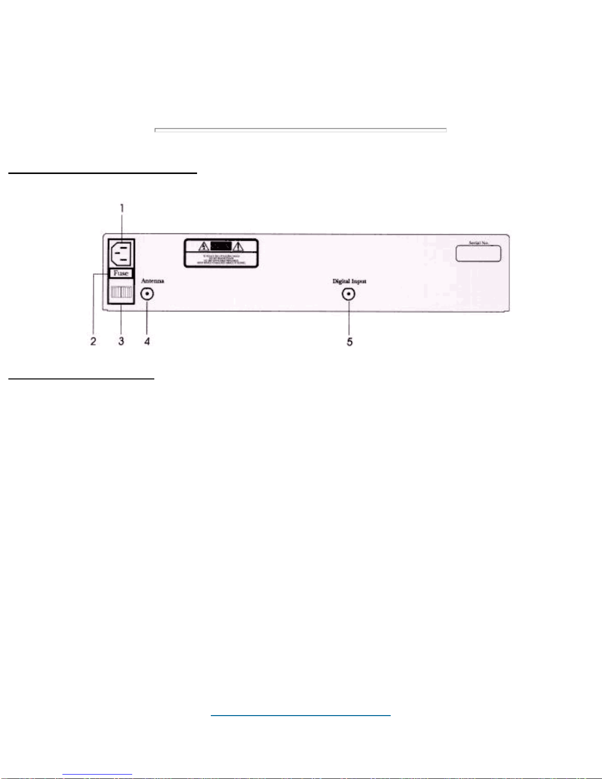
Digital Transmitter - Back
Legend for Transmitter - Back
1. Power Input Connector
The power input connector brings 110 Volts 60 Hz AC into the system.
2. Main Line Fuse
Main system fuse for the Transmitter, 2 Amp 250 Volt Slow-Blow.
3. Main Power Switch
Switches power for the Transmitter
4. Antenna Connector
Connector for Transmitter antenna.
5. Digital Input Connector
Connector for coax cable.
Click here to go back to the Index.

Upper Monitor
Legend for Upper Monitor
1. Channel Display
Indicates current channel selected
2. Channel Select
To select the desired listening channel
3. Volume Adjust
To select the desired listening volume.
4. Mute
Audio mute.
5. Headphone Jack
Standard 3.5 mm headphone jack.
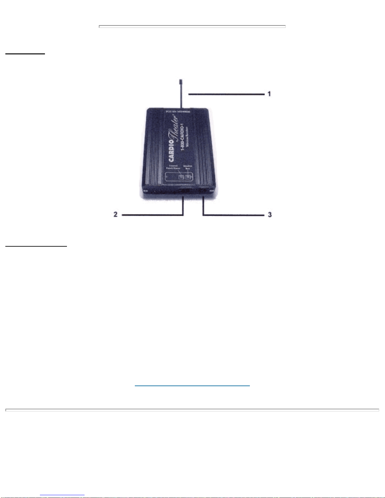
Receiver
Legend for Receiver
1. Antenna
Receives signal from Digital Transmitter.
2. Power Connector
Connector for Power.
3. Monitor Box Connector
Connector for Coiled Cable to Upper Monitor.
Click here to go back to the Index.
System Connections
NOTE:
** The Cardio Theater Digital Transmitter works together with the Cardio Theater Main Amplifier. The Cardio Theater
Main Amplifier is shipped separately and is supplied with its own Installation Manual.
** Before continuing with this Installation of the Digital Transmitter and Receivers, please refer to the Cardio Theater
Main Amplifier Instruction Manual pages 9 - 12. Make all connections and adjustments to the Main Amplifier before
proceeding with this installation.
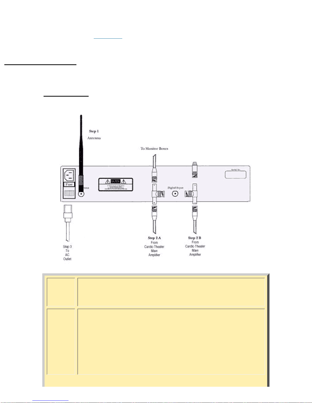
Digital Transmitter
NOTE: MAKE ALL CONNECTIONS TO DIGITAL TRANSMITTER AND RECEIVERS
WITH THE POWER OFF.
Step 1 ❍Connect the Antenna to the Antenna Connector as shown
in Step 1 of diagram above.
Step 2A
or
Step 2B
❍If there is no unused output connection on the Cardio
Theater Main Amplifier, install the eight inch (8")Coax with
T Connector as shown in Step 2A; OR:
❍If there is an unused output connection on the Cardio
Theater Main Amplifier, install the eight inch (8") Coax to
the digital input on the Wireless Transmitter as shown
above in Step 2B.
Ce manuel convient aux modèles suivants
1
Table des matières
Autres manuels Cardio Theater Récepteur


