
Cansec MAP1 Instructions d'utilisation et d'entretien
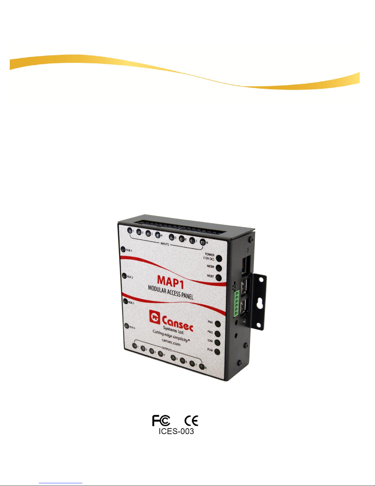
MAP1 Controller
INSTALLATION MANUAL
June 2018

MAP1 Page 2 of 31
Installation Manual June 2018 • Rev. 1.6
Table of Contents
Introduction ..................................................................................................................................................................3
Specifications..............................................................................................................................................................4
MAP1 Controller Layout..........................................................................................................................................7
Panel Installation......................................................................................................................................................10
Controller Power Connection.........................................................................................10
Entry Reader Wiring ........................................................................................................11
Entry and Exit Reader Wiring.........................................................................................12
Exit Button and Door Contact Wiring............................................................................12
Lock Output and Multi-Function Relay Wiring.............................................................15
Input and Output Point Wiring .......................................................................................17
Appendix......................................................................................................................................................................20
MAP1 System Indicators.................................................................................................21
Power Connector.............................................................................................................22
PB1 –Shutdown Button..................................................................................................23
PB2 –IP Reset Button and Static IP Address Configuration.....................................23
USB IP Configuration Tool..............................................................................................26
Forced Entry Output........................................................................................................30
Door Held Open Output...................................................................................................30
Alarm Shunt Output.........................................................................................................30
Door Operator Output –All Cards.................................................................................31
Door Operator Output –Handicap Cards only.............................................................31
Copyright 2018 Cansec Systems Ltd.
All rights reserved.

MAP1 Page 3 of 31
Installation Manual June 2018 • Rev. 1.6
Introduction
Cansec Systems’MAP1 (Modular Access Panel) incorporates a mini-computer
called the Panel Logic Module (PLM) utilizing Ethernet connectivity and an Input
Output Module (IOM) which incorporates a 32-bit processor in this new
architecture. This allows for a fast, high capacity access control system with a lower
cost per reader/door system implementation. The MAP1 architecture has the ability
to flash applications and firmware updates into the control panel using the
Ethernet connection.
The standard MAP1 is factory provisioned for two doors in First Access mode.
Door provisioning and mode (First Access –application based or Webster –web
based or Cloud Lock –cloud based) can be changed with a provisioning file provided
by Cansec upon purchase. Only one mode can be run at a time and data cannot be
shared between modes. Input and Output points are available when not used on a
provisioned door.
Note
: I/O points may be available in future release of Webster and
Cloud Lock.
The MAP1 allows for 100,000 individual cardholders, using raw Wiegand data up
to 64 bits per card ID. This allows the use of many proprietary Wiegand cards
without the need for data conversion. The readers can be Cansec’s CanProx One
Proximity Readers (AWID or HID card technology) or one of many other popular
Wiegand readers.
Note: Must have latest approved PLM and IOM firmware version for compatibility to this document.
255 Access Schedules
On board Triggers independent of host connection
Supports 100,000 individual user card IDs
Supports any Wiegand card (64 bit max.)
Supports up to 4 readers/door combinations
Supports Door Contact and RTE connection per reader/door
Supports Input points (with or without supervision) and Output points
Ease of future software/firmware upgrades
First Access mode or Webster mode or Cloud Lock mode
Key Features

MAP1 Page 4 of 31
Installation Manual June 2018 • Rev. 1.6
Specifications
See power supply notes in Appendix section for more information.
Controller Power Requirements (No Readers Attached, Ethernet Connected)
Maximum Current (all Relays, LEDs ON)………………………………… 350 mA
Temperature Range
Operating……………………………………………………………………………….. -20˚C to 60˚C
Relative Humidity
Operating ………………………………………………………..……………………… 20% to 80%
Auto Resettable Fuses
MAP1 Main 12V DC……………………………………………………………………………1 A
Each Reader Pair ……………………………………………………………………………………1 A
Output Relays
All Relays (8 per panel) Form ‘C’ …………………………………SPDT 6 A @ 30 VDC
Inputs per Provisioned Doors (Supervised or Non-Supervised)
Door Contact (2 per MAP1) …………………………Requires normally closed contact
(On/Off door switch)
Exit Button (2 per MAP1) ………………..………………Requires normally open contact
(Momentary push button switch)
Reader Cable
Wiegand Readers........................................ 6 conductor (twisted pair not required)
.............................................................................. 22 AWG, overall shield
........................................................................ 152 m [500 ft] max. Length
NOTE: Consult reader specifications as 18-gauge wire may be required for power
Dimensions & Weight
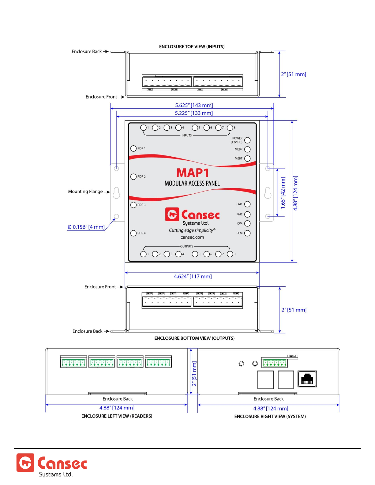
MAP1 Enclosure ……………………………………………..4.6” (W) x 4.9” (H) x 2.0” (D)
[11.7 cm (W) x 12.4 cm (H) x 5.1 cm D)]
Enclosure plus Controller Weight..................................................... 500 g [17.6 oz]
MAP1 Page 5 of 31
Installation Manual June 2018 • Rev. 1.6
Note: Specifications subject to change without notice.

MAP1 Page 6 of 31
Installation Manual June 2018 • Rev. 1.6
NOTE: Tech Support will only be provided where product installation guidelines
have been followed.
Specification Notes
CAUTION: EMERGENCY LOCKDOWN
Emergency lockdown functions must operate totally independent of the access
control system and must not rely on operation of card readers, access control
panels, communications networks, communications devices or host software.
Cansec accepts no responsibility for direct or consequential damages resulting from
the failure of emergency lockdown functions which are dependant in any way on
the operation of card readers, access control panels, communications networks,
communications devices or host software.
Wiring Note:
Improper Wiegand cable (new or originally installed cable or missing required
shield connections) may result in high frequency noise on the data lines creating
misreads. This Wiegand misread issue is more evident on longer Wiegand reader
cables. The reader cable may have to be replaced with the correct type of Wiegand
reader cable to improve system reliability.
MAP1 and H1000 Connector Compatibility:
H1000 connectors can be used on the MAP1 controller. The wiring will have to be
adjusted to accommodate for the reversed connector insertion.

MAP1 Page 7 of 31
Installation Manual June 2018 • Rev. 1.6
MAP1 Controller Layout
Figure 1

MAP1 Page 8 of 31
Installation Manual June 2018 • Rev. 1.6
Important Installation Notes
Controller Provisioning Options:
The MAP1 controller is factory provisioned with default 2-door configuration running
in First Access mode (First Access software is needed –database stored on computer). The
Webster mode (Web based –database stored on panel and no software is needed) and the
Cloud Lock mode (Cloud based –database stored on cloud server) can be enabled with an
authorized provisioning file obtained from Cansec upon purchase. The MAP1 can run
only in one mode at a time and can also be provisioned in one of two options below.
1. Door controller with or without auxiliary input and output points
a. 2–door configuration: 2 lock relays, 2 multi-function relays, 2 REX/RTE, 2
door contacts/DPS, 4 input points and 4 output points.
OR
b. 4–door configuration: 4 lock relays, 4 multi-function relays, 4 REX/RTE, 4
door contacts/DPS, 0 input points and 0 output points.
2. Input and Output controller only. 8 input and 8 output points available. No
door combination i.e. no lock relay and no multi-function relay.
Electrical Information:
1. The MAP1 utilizes a mini-computer and must be operated using a battery
backed up power supply to protect the hardware, system files and data files
from corruption due to power outage. See Note 1 in Appendix section.
2. CAUTION: Do not unplug the MAP1 Power connector if the system is in
operation as data corruption may occur on the MAP1 mini-computer. Please
follow the instructions from the section “PB1 - Shut Down”.
Figure 2

MAP1 Page 9 of 31
Installation Manual June 2018 • Rev. 1.6
3. The MAP1 allows for the control of up to 4 door combinations. Ensure that
adequate 12V DC power and current is available, especially when the same
power supply is used for the locks.
4. It is highly recommended to use a separate power supply for locks as they
require a high amount of current for proper operation.
Network Information:
1. The MAP1 Controller is set to acquire an IP address automatically (DHCP).
However, it can be optionally set to a static IP address or reset if necessary. See
Appendix section for more information.
Mechanical Information:
1. The MAP1 has 2 horizontal mounting flanges, which should be used to
attach the product to a stable surface.
2. If required the MAP1 may be mounted inside of a lockable enclosure such as
the CA-SLBOX or CA-H1000ENCL if access is to be limited to the external
connections.
3. If a Lockable external enclosure is used and a Tamper switch is available as in
the CA-SLBOX or CA-H1000ENCL, the MAP1 has a Panel Tamper input
connection available. Connecting the Tamper switch, See figure 14, to this
input will produce an Alarm when opening and closing the enclosure. This
Alarm is sent to the Host computer.

MAP1 Page 10 of 31
Installation Manual June 2018 • Rev. 1.6
Panel Installation
CONTROLLER POWER CONNECTION
Note: See Note 1 in Appendix section for suggested power supplies & backup battery.
The MAP1 requires an external battery backed-up 12 VDC power supply. However,
as many devices can be attached to the MAP1 controller, it may be more cost
effective to use a separate power supply (battery backed-up) just for the MAP1
Controller and a separate power supply which can be sized to supply the amount of
current that the attached high-current devices (locks) will require.
Figure 3
Mode Indicator: After a complete power up, PM1 LED is on, PM2 LED is off, IOM LED flashes
once every second, PLM LED flashes waiting for a host connection and stays
steady when a connection is established. MAP1 emits beep to indicate
operating mode.
1 Beep –First Access
2 Beeps –Webster
3 Beeps –Cloud Lock
Autres manuels pour MAP1
1
Table des matières
Autres manuels Cansec Contrôleurs

Cansec
Cansec H1000 Manuel utilisateur

Cansec
Cansec SMARTLOCK Series Manuel utilisateur

Cansec
Cansec Canlan M200 Manuel utilisateur

Cansec
Cansec CP40 Manuel utilisateur

Cansec
Cansec MAPMINI Controller Manuel utilisateur

Cansec
Cansec MAP2 Manuel utilisateur

Cansec
Cansec Webster 64 Manuel utilisateur

Cansec
Cansec H1000 Manuel utilisateur


