CAN PCAN-PCI Manuel utilisateur
PCAN-PCI
CAN Interface for PCI
User Manual
Document version 2.3.1 (2014-04-29)

PCAN-PCI – User Manual
2
Products taken into account
Product Name Model Part Number
PCAN-PCI Single Channel One CAN channel IPEH-002064
PCAN-PCI Dual Channel Two CAN channels IPEH-002065
PCAN-PCI Single Channel
opto-decoupled
One CAN channel, galvanic
isolation for CAN connection
IPEH-002066
PCAN-PCI Dual Channel
opto-decoupled
Two CAN channels, galvanic
isolation for CAN connections
IPEH-002067
The cover picture shows the product PCAN-PCI Dual Channel opto-decoupled. Other
product versions have an identical form factor but vary in equipment.
CANopen® and CiA® are registered community trade marks of CAN in Automation
e.v.
All other product names mentioned in this manual may be the trademarks or
registered trademarks of their respective companies. They are not explicitly marked
by “™” and “®”.
© 2014 PEAK-System Technik GmbH
PEAK-System Technik GmbH
Otto-Roehm-Strasse 69
64293 Darmstadt
Germany
Phone: +49 (0)6151 8173-20
Fax: +49 (0)6151 8173-29
www.peak-system.com
info@peak-system.com
Document version 2.3.1 (2014-04-29)

PCAN-PCI – User Manual
3
Contents
1Introduction 4
1.1 Properties at a Glance 4
1.2 System Requirements 5
1.3 Scope of Supply 5
2Installing the Software and the Card 6
3Connecting the CAN Bus 9
3.1 D-Sub Connector 9
3.2 Supplying External Devices via the CAN
Connector 10
3.3 Cabling 12
3.3.1 Termination 12
3.3.2 Example of a Connection 12
3.3.3 Maximum Bus Length 13
4Using the Software 14
4.1 CAN Monitor PCAN-View for Windows 14
4.1.1 Receive/Transmit Tab 16
4.1.2 Trace Tab 18
4.1.3 Status Bar 19
4.2 Linking Own Programs with PCAN-Basic 20
4.2.1 Features of PCAN-Basic 21
4.2.2 Principle Description of the API 22
4.2.3 Notes about the License 23
5Technical Specifications 24
Appendix A CE Certificate 26
Appendix B Dimension Drawing 27
Appendix C Quick Reference 28

PCAN-PCI – User Manual
4
1Introduction
The PCAN-PCI card enables the connection of a PC with PCI slots to
CAN networks. The opto-decoupled versions also guarantee
galvanic isolation of up to 500 Volts between the PC and the CAN
sides. Device drivers and programming interfaces exist for different
operating systems, so programs can easily access a connected CAN
bus.
Tip: At the end of this manual (Appendix C) you can find a
Quick Reference with brief information about the installation
and operation of the PCAN-PCI card.
1.1 Properties at a Glance
PC plug-in card for PCI slot
1 or 2 High-speed CAN channels (ISO 11898-2)
Bit rates from 5 kbit/s up to 1 Mbit/s
Compliant with CAN specifications 2.0A (11-bit ID)
and 2.0B (29-bit ID)
CAN bus connection via D-Sub, 9-pin
(in accordance with CiA® 102)
NXP SJA1000 CAN controller, 16 MHz clock frequency
NXP PCA82C251 CAN transceiver
Galvanic isolation on the CAN connection up to 500 V (only
opto-decoupled versions), separate for each CAN channel
5-Volts supply to the CAN connection can be connected through
a solder jumper, e.g. for external bus converter

PCAN-PCI – User Manual
5
Extended operating temperature range from -40 to 85 °C
(-40 to 185 °F)
Note: This manual describes the use of the PCAN-PCI card with
Windows. You can find device drivers for Linux and the
corresponding application information on the provided DVD in
the directory branch Develop and on our website under
www.peak-system.com/linux.
1.2 System Requirements
A vacant PCI slot in the computer
Operating system Windows 8, 7, Vista (32/64-bit)
or Windows CE 6.x (x86 and ARMv4 processor support)
or Linux (32/64-bit)
1.3 Scope of Supply
PCAN-PCI card
Device drivers for Windows 8, 7, Vista and Linux (32/64-bit)
Device driver for Windows CE 6.x
(x86 and ARMv4 processor support)
PCAN-View CAN monitor for Windows 8, 7, Vista (32/64-bit)
PCAN-Basic programming interface consisting of an interface
DLL, examples, and header files for all common programming
languages
Manual in PDF format

PCAN-PCI – User Manual
6
2Installing the Software and
the Card
This chapter covers the software setup for the PCAN-PCI card under
Windows and the installation of the card in the computer.
Setup the driver before installing the PCAN-PCI card.
Do the following to install the driver:
1. Make sure that you are logged in as user with administrator
privileges (not needed for normal use of the PCAN-PCI card
later on).
2. Insert the supplied DVD into the appropriate drive of the
computer. Usually a navigation program appears a few
moments later. If not, start the file Intro.exe from the root
directory of the DVD.
3. On the page English > Drivers activate the entry PCAN-PCI.
4. Click on Install now. The setup program for the driver is
executed.
5. Follow the instructions of the setup program.
Tip: If you don't want to install the CAN monitor PCAN-View for
Windows onto the hard disk together with the driver, you have
the option to start the program later directly from DVD without
prior installation.
PCAN-PCI – User Manual
7
Do the following to install the PCAN-PCI card in the computer:
Attention! Electrostatic discharge (ESD) can damage or destroy
components on the PCAN-PCI card. Take precautions to avoid
ESD when handling the card.
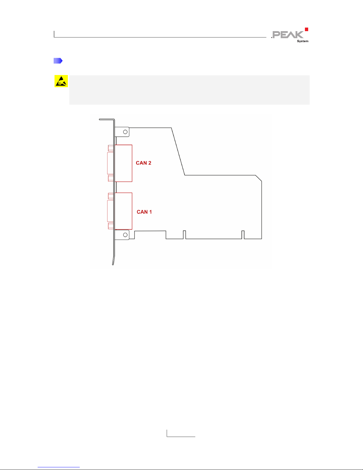
Figure 1: Position of the CAN connectors CAN 1 (lower position)
and CAN 2 (upper position). In the Single Channel version,
CAN 1 remains at the same position
1. Shut down the computer.
2. Disconnect the computer from the power supply.
3. Open the computer's casing.
4. Insert the PCAN-PCI card into an empty PCI slot. For details
please refer to the documentation of the computer.
5. Close the computer's casing.
6. Reconnect the power supply of the computer.

PCAN-PCI – User Manual
8
Do the following to complete the initialization:
1. Turn on the computer and start Windows. Make sure that
you are logged in as user with administrator privileges.
Windows notifies that new hardware has been detected.
2. The drivers are found and installed by Windows.
3. Afterwards you can work as user with restricted rights
again.
After the initialization process is finished successfully you can find
the entry “PCAN-PCI” in the branch “CAN-Hardware” of the
Windows Device Manager.
PCAN-PCI – User Manual
9
3Connecting the CAN Bus
3.1 D-Sub Connector
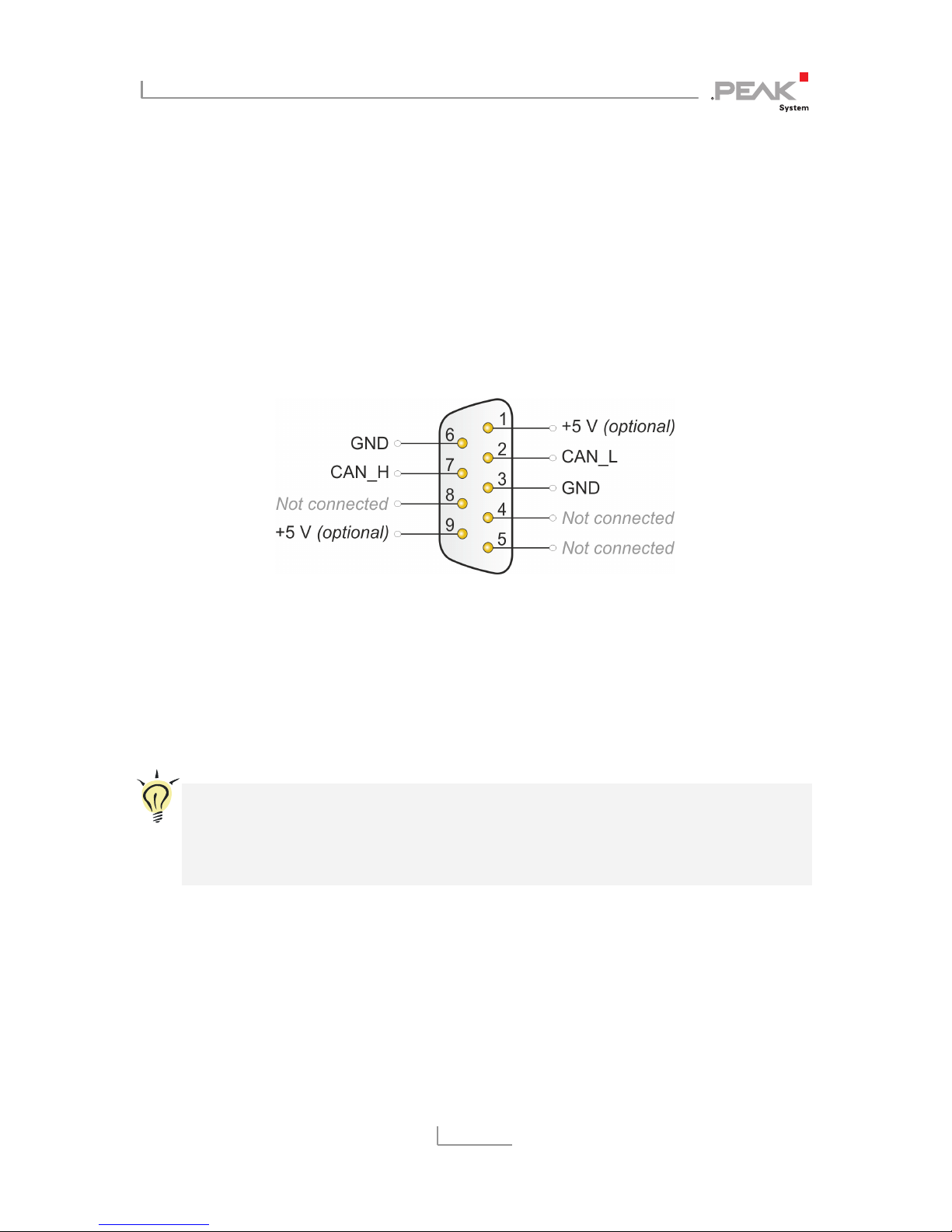
A High-speed CAN bus (ISO 11898-2) is connected to the 9-pin
D-Sub connector. The pin assignment for CAN corresponds to the
specification CiA® 102.
Figure 2: Pin assignment of High-speed CAN connection
(view onto a male connector on the PCAN-PCI card)
With the pins 1 and 9 devices with low power consumption (e.g. bus
converters) can be directly supplied via the CAN connector. At deli-
very these pins are not assigned. You can find a detailed description
in the following section 3.2.
Tip: You can connect a CAN bus with a different transmission
standard via a bus converter. PEAK-System offers different bus
converter modules (e.g. PCAN-TJA1054 for a Low-speed CAN
bus according to ISO 11898-3).

PCAN-PCI – User Manual
10
3.2 Supplying External Devices via the CAN
Connector
A 5-Volt supply can optionally be routed to pin 1 and/or pin 9 of a D-
Sub connector by setting solder bridges on the PCAN-PCI card
(independently for each connector on the Dual Channel versions).
Thus devices with low power consumption (e.g. bus converters) can
be directly supplied via the CAN connector.
When using this option the 5-Volt supply is connected to the power
supply of the computer and is not fused separately. The opto-
decoupled versions of the card contain an interconnected DC/DC
converter. Therefore the current output is limited to about 50 mA.
Proceed as follows to activate the 5-Volt supply:
Attention! Electrostatic discharge (ESD) can damage or destroy
components on the PCAN-PCI card. Take precautions to avoid
ESD when handling the card.
Set the solder bridge(s) on the PCAN-PCI card according to the
desired settings. During this procedure take especially care not to
produce unwanted short circuits on the card.
Figure 3 shows the positions of the solder fields on the PCAN-PCI
card. The table below contains the possible settings.
Table des matières
Manuels Carte PCI populaires d'autres marques


Belkin
Belkin F5D7000F Manuel utilisateur

Pericom
Pericom PI7C7100 Manuel utilisateur

ADLINK Technology
ADLINK Technology cPCI-3548 Manuel utilisateur

Digium
Digium TE200 Series Manuel utilisateur

Allo.com
Allo.com 2nd Gen E1/T1/J1 Manuel utilisateur

Western Digital
Western Digital FireWire PCI Adapter Manuel utilisateur