C-SCOPE Function Checker Manuel utilisateur

Instruction Manual
Function Checker
PRECI ION PIPE AND CABLE LOCATION

WAR I GS / OTES
2
WARNING The Function Checker does not recalibrate, service or repair any C.Scope Cable Avoidance Tool,
Locator, Signal Generator or Transmitter. The Function Checker does confirm if the C.Scope product is fit for use.
WARNING If a C.Scope Locator, Signal Generator or Transmitter fails any of the Condition Checks or
Performance Checks detailed in this manual then it should be withdrawn from service immediately and
returned to a C.Scope Authorised Service Centre.
NOTE In order to be able to carry out Performance Checks using the Function Checker, it is necessary to be
familiar with the operation of the C.Scope equipment that is to be checked. Training is available from C.Scope
comprising the full and correct use of all C.Scope location equipment (see page 78).
WARNING Only use the Function Checker in an area that has been scanned and found to be suitable for use,
as described on page 8 in the ‘Selecting a suitable location’ section.

Contents
Warnings 2
Introduction 4
Using t is Manual 5
Features 6-7
Selecting a suitable location 8
CONDITION CHECK
C.SCOPE LOCATORS
CABLE AVOIDA CE TOOL / XD
CXL / DXL
MXL 9-10
CONDITION CHECK
C.SCOPE
SIGNAL GENERATORS
AND TRANSMITTERS
SGA Signal Generator Black / Grey
SGV Signal Generator Black / Grey
MXT
Signal Generator pre 2003 11-12
PERFORMANCE CHECK
C.SCOPE LOCATORS
CABLE AVOIDA CE TOOL / XD 14-19
TABLE 20-21
CXL / DXL 22-27
TABLE 28-29
MXL 30-37
TABLE 38-41
PERFORMANCE CHECK
C.SCOPE
SIGNAL GENERATORS
AND TRANSMITTERS
SGA Signal Generator
Black / Grey 43-47
TABLE 48-49
SGV Signal Generator
Black / Grey 50-55
TABLE 56-57
MXT 58-65
TABLE 66-67
Signal Generator pre 2003 68-73
TABLE 74-75
Maintenance/General Symbols 76
Tec nical Specification 77
Support Services
Training/Servicing/Repairs 78
3

4
Introduction
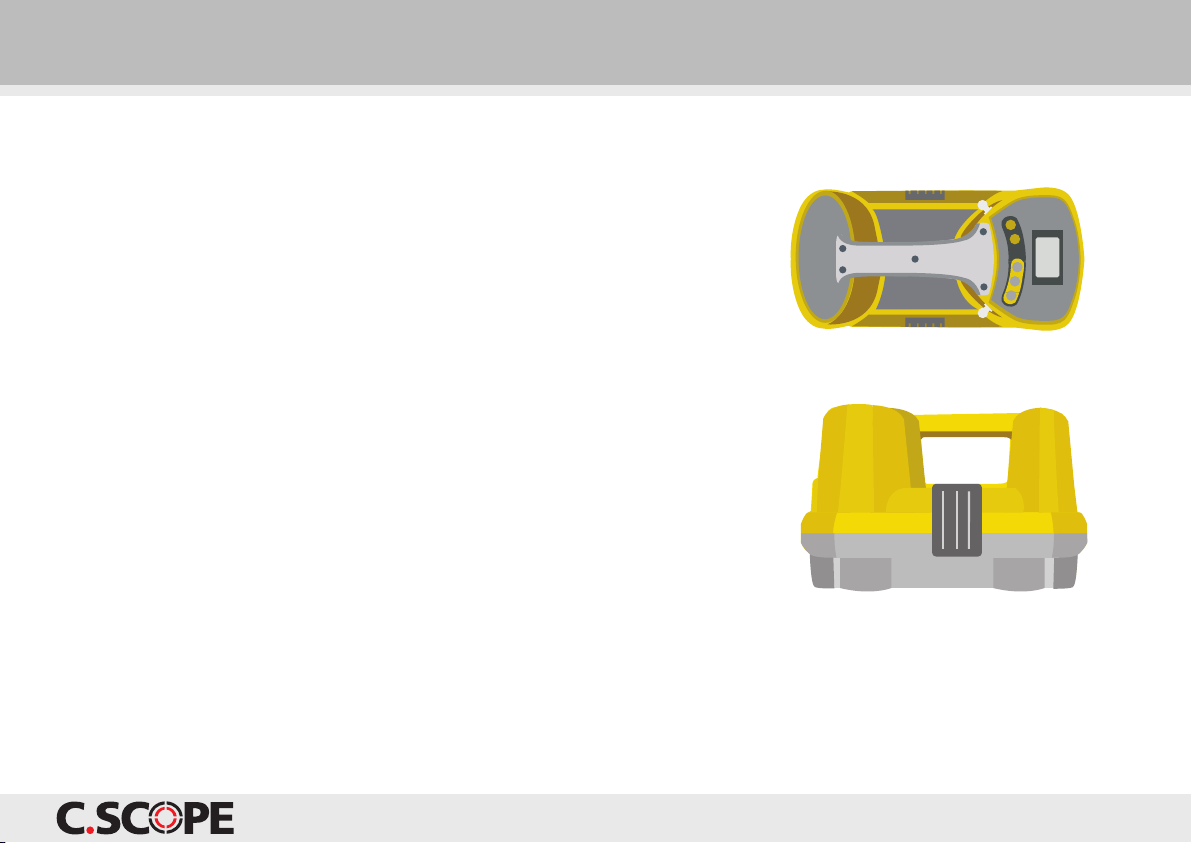
The C.Scope Function Checker is a simple-to-use product
that allows the performance of C.Scope Cable Avoidance
Tools, Locators, Signal Generators and Transmitters to
be checked.
The robust and portable Function Checker is battery
operated, and designed for use in a variety of locations
such as at a depot or out on site. It can test a wide
range of C.Scope equipment, to confirm that they are
operating correctly.
The Function Checker will not identify if a C. cope
product has suffered any form of mechanical damage
that has compromised its structural integrity or ability
to withstand water or dust ingress UNLE that damage
has also affected electronic performance. The ‘Condition
Checks’ also detailed in this Manual are an essential part
of the checking process to identify such damage and
MU T be carried out on every unit.
It is important to note that the Function Checker does
not recalibrate, service, repair or alter in any way, the
operation of any C.Scope product.
Correct use of the Function Checker allows the operator
to confirm that the product is detecting the signals it is
designed to detect (in the case of C.Scope Locators) or
transmitting the signals it is designed to transmit (in the
case of C.Scope Signal Generators and Transmitters).
The following C.Scope products are covered in this manual:
C.Scope CXL Locator
C.Scope DXL Locator
C.Scope MXL Locator
C.Scope Cable Avoidance Tool
C.Scope Cable Avoidance Tool XD
C.Scope grey SGA Signal Generator
C.Scope black SGA Signal Generator
C.Scope grey 1Watt SGV Signal Generator
C.Scope black SGV Signal Generator
C.Scope MXT Transmitter
C.Scope Signal Generator (pre 2003)
WARNING If a C.Scope product fails any of the Condition Checks or Performance Checks then it should be withdrawn
from service immediately and returned to a C.Scope Authorised Service Centre.

5
Using this Manual
The Function Checker allows Performance Checks to be carried out
on a wide range of C.Scope Cable Avoidance Tools, Locators, Signal
Generators and Transmitters with each model covered in a specific
section of this manual. It is essential to identify exactly which C.Scope
product you wish to test before attempting any of the Checks.
All C.Scope products should undergo two distinct types of checking:
‘Condition Checks’ and ‘Performance Checks’. This manual has
sections devoted to both of these procedures and it is important that
both are carried out for every product.
The ‘Condition Checks’ should always be completed before the
‘Performance Checks’.
Condition Checks for all C.Scope Locators are covered in the section
‘Condition Checks C.Scope Locators’ on pages 9-10. Condition Checks
for all C.Scope Signal Generators or Transmitters are covered in the
section ‘Condition Checks C.Scope Signal Generators and
Transmitters’ on pages 11-12.

Terminals.
Control buttons.
Liquid Crystal Display (LCD)
The Function Checker LCD indicates:
Operating frequency (where appropriate).
Power mode.
Radio mode.
Method of Testing.
Battery condition.
Signal levels received when testing
Signal Generators or Transmitters.
6
Features

7
Features
ON/OFF
The Function Checker will automatically turn off five minutes
after the last button press.
MODE
Selects and cycles through the four modes of operation:
for testing the induced output signal of C.Scope Signal
Generators and Transmitters.
for testing connected output signal of C.Scope Signal
Generators and Transmitters.
for testing the CXL, DXL and MXL Locators.
for testing the Cable Avoidance Tool
and Cable Avoidance Tool XD.
POWER
Selects the Power test signal for Locator testing.
RADIO
Selects the Radio test signal for Locator testing.
FREQUENCY
Selects the Generator/Transmitter Mode test signal for
Locator testing.

8
Selecting a suitable location
In order for the Function Checker to correctly Performance Check a C.Scope product it is important that
there are no strong background electromagnetic signals present that may cause interference. Therefore,
the intended location for using the Function Checker should be checked for background electromagnetic
signals before use.
This can be achieved by scanning the area using the Power and Radio Modes of a Locator. If the Locator
indicates no large power or radio signals then the area should be suitable for Function Checker testing.
(Generally, ‘large’ signals are those that are detectable with the Locator sensitivity control set at 50% or
less on either mode).
NOTE
Electromagnetic signals can be caused or influenced by any of the following:
The operation of other Signal Generators/Transmitters and Sondes in the same area as the Function Checker.
earby electrical plant such as transformers or main switch boards.
Live overhead or underground electricity cables directly above or below the Function Checker.
Large metal objects such as steel workbenches or filing cabinets.
Vehicles or plant in close proximity to the Function Checker.
Metal-based flooring, including steel reinforced concrete.

Condition Checks C.Scope Locators
The following C.Scope Locators are covered
in this section:
C.Scope CXL Locator
C.Scope DXL Locator
C.Scope MXL Locator
C.Scope Cable Avoidance Tool
C.Scope Cable Avoidance Tool XD
The following Condition Checks MU T be carried out prior
to Performance Checking any C.Scope Locator with the
Function Checker. These Condition Checks are designed
to identify if there is any mechanical deterioration to the
Locator under test that may compromise performance or
make the product vulnerable to water or dust ingress.
If the Locator does not pass all of the Condition Checks
then it should be withdrawn from service immediately
and returned to a C. cope Authorised ervice Centre.
9
Loudspeaker
Display
O /OFF Switch
Sensitivity Control
Mode Switch
Battery Compartment
Labels
Wear Foot

10
1. Carefully inspect the Locator case for damage or
deterioration such as cracks or distortion.
2. Check all case securing screws are in place.
3. Check that the Wear Foot is in good condition and is
securely fixed to the Locator.
4. Examine the condition of all the labels ensuring they are
intact and all text is legible.
5. Check that the Loudspeaker can be unclipped from the
body, that the cable is undamaged and that the
Loudspeaker can be easily withdrawn and then refitted.
6. Examine the condition of the display for any cracks or
excessive scratching.
7. Check that the Sensitivity Control rotates freely over
three quarters of a turn without any binding and has a
definite stop position at each end.
8. Check that the Mode Switch has definite stop positions
for each mode.
9. Check that the O /OFF Switch operates smoothly and
does not stick.
10. Inspect the battery compartment for any sign of dirt
or water.
11. Ensure the Battery Cover is in place and locks tightly
shut and that the Battery Cover seal is in good condition.
12. Inspect the Battery Holder for deterioration, distortion
or corrosion. Replace if necessary.
13. Confirm that the spare Battery Holder is present
and inspect for deterioration, distortion or corrosion.
Replace if necessary.
14. Check that the batteries are in good condition. Replace
batteries if incorrectly fitted, damaged or corroded.
Condition Checks C.Scope Locators
NOTE It may be necessary to clean the Locator before performing the Condition Checks.
Table des matières


