Bronpi KIT-1 Manuel utilisateur

INSTRUCCIONES DE INSTALACIÓN, USO Y MANTENIMIENTO
KIT 1
INSTALLATION, OPERATING AND SERVICING INSTRUCTIONS
KIT 1
INSTRUCTIONS D’INSTALLATION, D’UTILISATION ET D’ENTRETIEN
KIT 1
INSTRUÇÕES DE INSTALAÇÃO, USO E MANUTENÇÃO
KIT 1
ISTRUZIONI DI INSTALLAZIONE, USO E MANUTENZIONE
KIT 1

ES
INSTRUCCIONES DE INSTALACIÓN,
USO Y MANTENIMIENTO
KIT - 1 4
EN
INSTALLATION, OPERATING
AND SERVICING INSTRUCTIONS
KIT - 1 7
FR
INSTRUCTIONS D’INSTALLATION,
D’UTILISATION ET D’ENTRETIEN
KIT - 1 10
PT
INSTRUÇÕES DE INSTALAÇÃO,
USO E MANUTENÇÃO
KIT - 1 13
IT
ISTRUZIONI DI INSTALLAZIONE,
USO E MANUTENZIONE
KIT - 1 16
CONDICIONES DE GARANTÍA
WARRANTY CONDITIONS
CONDITIONS DE LA GARANTIE
CONDIÇÕES DA GARANTIA
CONDIZIONI DI GARANZIA 19
V. 280515

4
KIT-1
Módulo para chimeneas con producción de agua caliente para uso en calefacción y sanitario
El KIT-1 es un módulo para la gestión de instalaciones de calefacción alimentadas por una chimenea o fuente alternativa para la producción
de agua caliente destinada a las instalaciones de calefacción doméstica y ACS.
La producción de ACS es prioritaria y viene automáticamente relevada del sistema hidráulico por mediación de un detector de flujo.
CARACTERÍSTICAS TÉCNICAS
Dimensiones
Longitud 402mm. Altura 190mm. Profundidad 250mm.
Características eléctricas
Alimentación 230Vac. Frecuencia 50Hz. Potencia absorbida 80W.
Conexiones hidráulicas
Racor chimenea calefactora G 3/4” - 1
Racor instalación G 3/4”
Racor sanitario G 1/2”
NORMATIVAS Y DIRECTIVAS
Conformidad a las normas:
• EN 60730-1 Y ACTUALIZACIONES SUCESIVAS
• EN 60730-2-9
Conformidad a la directiva:
• E.M.C. 2004/108/CE E.B.T: 2006/95/CE
INSTALACIONES Y CONEXIONES
Advertencia de seguridad
• Antes de conectar el módulo a la red eléctrica, cercionarse que la tensión de red esté desconectada y que corresponda a un valor de
230Va.c.
• Colocar en la instalación externa un reductor de presión o una válvula de seguridad por si la presión del circuito sanitario supera los
6 bars.
• Conectar la instalación hidráulica según las indicaciones reportadas sobre la plantilla e indicaciones del diseño.
INSTRUCCIONES DE INSTALACIÓN, USO Y MANTENIMIENTO KIT - 1
ES

5
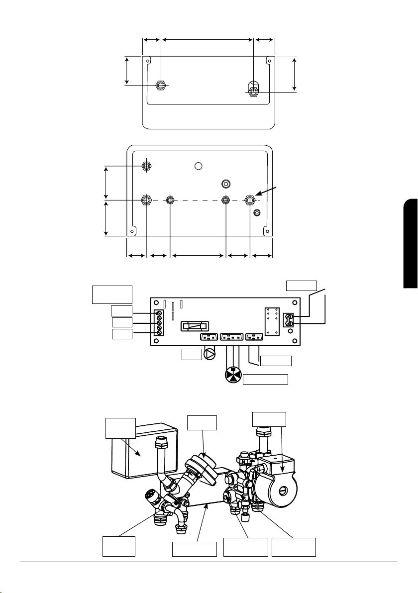
VISTA SUPERIOR
IDA
DE LA
CHIMENEA
RETORNO
DE LA
CHIMENEA
GRH 561534
284.5 64.556
100
122.5
VISTA INFERIOR
DESAGUE
VALVULA DE
LLENADO
IDA DE
CALEFACCIÓN RETORNO DE
CALEFACCIÓN
100 95
15465 65 64.556.5
ACS AFS
CONEXIONADO TARJETA ELECTRÓNICA
Sistema de
alimentación
L
N
L
NN
J1
J2
J4
J3 J8
J7
J10 J11 J12
K2
Tierra
Fase
Neutro
Bomba
Flujometro
Termostato
Desviador
COMPONENTES
Tarjeta
INTFH20
Actuador Circulador
Grupo Ida Intercambiador Detector de
flujo
Grupo
retorno
ES
INSTRUCCIONES DE INSTALACIÓN, USO Y MANTENIMIENTO KIT - 1

6
CIRCULADOR
Grupo
Ida
Conexión
Rápida vaso
de expansión
Purgador
automático
Grifo de
descarga
NOTA: El fabricante se reserva el derecho de efectuar modificaciones estéticas y/o funcionales sin preaviso.
INSTRUCCIONES DE INSTALACIÓN, USO Y MANTENIMIENTO KIT - 1
ES

7
KIT-1
Module for fireplaces with hot water production for sanitary and heating purpose.
KIT-1 is a module in order to manage heating installations fed by a fireplace or an alternative source for the production of sanitary hot water
for domestic heating and SHW installations.
SHW production is a priority and it works automatically through a flow detector.
TECHNICAL SPECIFICATIONS
Dimensions
Length 402mm. Height 190mm. Depth 250mm.
Electrical specifications
Power supply 230Vac. Frequency 50Hz. Power input 80W.
Hydraulic connections
Heating chimney fitting G 3/4” – 1
Installation fitting G 3/4”
Sanitary fitting G 1/2”
REGULATIONS AND DIRECTIVES
Accordance to regulations:
• EN 60730-1 AND LATER UPGRADES
• EN 60730-2-9
Accordance to directive:
• E.M.C. 2004/108/CE E.B.T: 2006/95/CE
INSTALLATIONS AND CONNECTIONS
Security advice
• Before connecting the module to the electrical network, please, verify that the network tension is disconnected and has a value of
230Va.c.
• A pressure reducer or a safety valve must be installed in order to avoid that the pressure inside the circuit is higher than 6 bars.
• Connect the hydraulic installation following the indications in the schema and design of the drawing.
EN
INSTALLATION, OPERATING AND SERVICING INSTRUCTIONS KIT - 1

8
TOP VIEW
THERMOSTOVE
FEED
THERMOSTOVE
RETURN
GRH 561534
284.5 64.556
100
122.5
BOTTOM VIEW
100 95
15465 65 64.556.5
ELECTRONIC CARD CONNECTION
Feeding
system
L
N
L
NN
J1
J2
J4
J3 J8
J7
J10 J11 J12
K2
Ground
Phase
Neutral
Pump
Flowmeter
Thermostat
Diverter Valve
COMPONENTS
Card
INTFH20
Actuator Circulator
Flow group Exchanger Flow
sensor
Return
group
DRAINPIPE
DRAINPIPE
TAP
INSTALLATION
FEED
INSTALLATION
RETURN
SHW SHW
EN
INSTALLATION, OPERATING AND SERVICING INSTRUCTIONS KIT - 1

9
CIRCULATOR
Flow
group
Fast
connection
expansion
vessel
Daerator
automatic
Download
tap
NOTE: The manufacturer reserves the right to make esthetical and functional modifications without prior notice.
EN
INSTALLATION, OPERATING AND SERVICING INSTRUCTIONS KIT - 1

10
KIT-1
Module pour chaudières avec production d'eau chaud pour l’usage dans chauffage et sanitaire
Le KIT-1 est un module pour la gestion d'installations de chauffage alimentés par une chaudière ou une source alternative pour la production
d'eau chaude destinée aux installations de chauffage domestique et d'ECS.
La production d'ECS est prioritaire et vient de façon automatique relevé du système hydraulique à travers d'un détecteur de flux.
CARACTÉRISTIQUES TECHNIQUES
Dimensions
Longueur 402mm. Hauteur 190mm. Profondeur 250mm.
Caractéristiques électriques.
Alimentation 230Vac. Fréquence 50Hz. Puissance absorbée 80W.
Connexions hydrauliques
Raccord cheminée chauffante G 3/4” – 1
Raccord installation G 3/4”
Raccord sanitaire G 1/2”
NORMATIVES ET DIRECTIVES
Conformité aux normes:
• EN 60730-1 ET DES FUTURS ACTUALISATION
• EN 60730-2-9
Conformité à la directive:
• E.M.C. 2004/108/CE E.B.T: 2006/95/CE
INSTALLATIONS ET CONNEXIONS
Avertissement de sécurité
• Avant connecter le module au réseau électrique, vérifier que la tension du réseau est déconnectée et
• qui a une valeur de 230 Va.c.
• Placer à l'installation externe un réducteur de pression ou une soupape de sécurité pour éviter que la pression du circuit sanitaire
dépasse les 6 bars.
• Connecter l'installation hydraulique selon les indications signalés sur la guide et les indications du design.
FR
INSTRUCTIONS D’INSTALLATION, UTILISATION ET ENTRETIEN KIT - 1
11
VUE SUPÉRIEURE
ALLÉE
THERMOPOÊLE
RETOUR
THERMOPOÊLE
GRH 561534
284.5 64.556
100
122.5
VUE INFÉRIEURE
ECS ECS
DÉVERSOIR ROBINET
DU
DÉVERSOIR
ALÉE
INSTALLATION RETOUR
INSTALLATION
100 95
15465 65 64.556.5
CONNECTION CARTE ELÉCTRONIQUE
Système
d’alimentation
L
N
L
NN
J1
J2
J4
J3 J8
J7
J10 J11 J12
K2
Terre
Phase
Neutre
Pompe
Débitmétre
Thermostat
Valve déviatrice
COMPOSANTS
Carte
INTFH20
Acteur Circulateur
Groupe
allée Échangeur Detecteur
de flux
Group
retour
FR
INSTRUCTIONS D’INSTALLATION, UTILISATION ET ENTRETIEN KIT - 1
Table des matières
Langues :
Manuels Accessoires de cheminée populaires d'autres marques


Town & Country Fireplaces
Town & Country Fireplaces 22150051 Manuel utilisateur

Travis Industries
Travis Industries 33 DVI Manuel utilisateur

Superior
Superior ASD3628-TI Manuel utilisateur

pleasant hearth
pleasant hearth OFP28WG Manuel utilisateur

IHP
IHP Astria Series Manuel utilisateur

Firegear
Firegear FG-H-2110SS Manuel utilisateur

Nibe
Nibe Contura C i31 Manuel utilisateur

kozy heat
kozy heat KZK-052 Manuel utilisateur

SimpliFire
SimpliFire SF-WM36 Manuel utilisateur

Bluegrass Living
Bluegrass Living BC18NR Guide de démarrage rapide

pleasant hearth
pleasant hearth IRIS SCROLL Manuel utilisateur

Cooke
Cooke Glass Wind Guard Manuel utilisateur