Contents
Read me first......................................................................................................... 3
Avoiding malfunction and damage..............................................................................................4
What’s in the box..............................................................................................................................5
Installation..............................................................................................................6
Connection overview........................................................................................................................7
Choosing the correct osition.......................................................................................................8
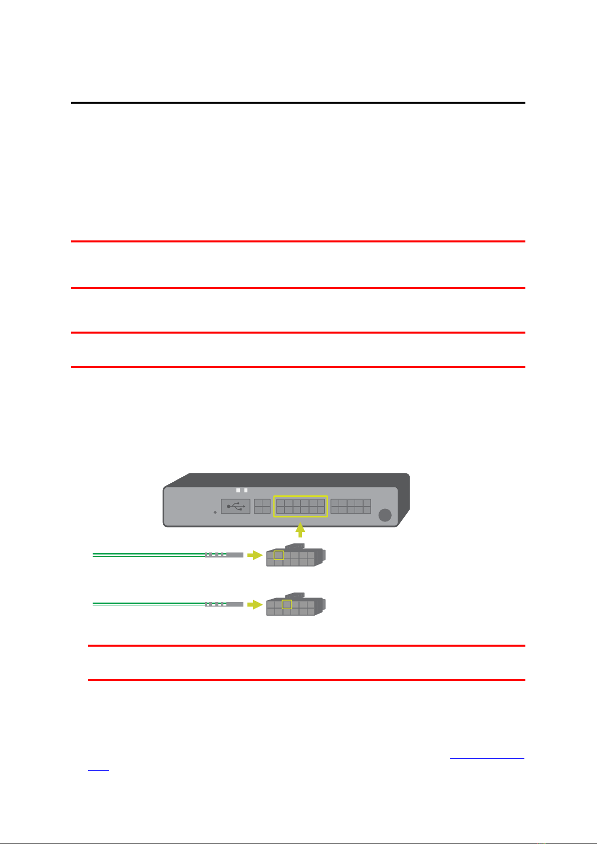
Wiring the PRO i...............................................................................................................................9
Configuring the PRO i in Webfleet............................................................................................ 10
Configuring the PRO i in the LINK Toolkit a ........................................................................11
Mounting the PRO i........................................................................................................................ 12
Attaching the P O i using the adhesive strip........................................................................... 12
Attaching the P O i to the air vent.............................................................................................. 13
Su ort...............................................................................................................................................14
Technical data.................................................................................................................................. 15
Com liances......................................................................................................................................16
Addendum............................................................................................................ 17
Im ortant safety notices and warning.......................................................................................18
CE/UK mark and Radio Equi ment Directive..........................................................................19
Triman logo......................................................................................................................................20
WEEE – e-waste dis osal.............................................................................................................20
FCC information for the user......................................................................................................20
Technical S ecifications................................................................................................................ 21
O erating tem erature................................................................................................................. 22
Model numbers................................................................................................................................22
Usable with.......................................................................................................................................22
Accessories not su lied with this device.............................................................................. 22
Accessories su lied with this device...................................................................................... 22
REACH statement – Webfleet..................................................................................................... 22
RoHS statement – Webfleet........................................................................................................ 23
Res onsible arty in the United Kingdom...............................................................................23
Res onsible arty in North America......................................................................................... 23
Res onsible arty in Chile........................................................................................................... 23
Customer su ort contact........................................................................................................... 23
Emissions information for Canada............................................................................................. 23
Chile....................................................................................................................................................24
Certification for Australia.............................................................................................................24
Warning for Australia....................................................................................................................24
Notice for New Zealand................................................................................................................24
Customer su ort contact (Australia and New Zealand).................................................... 24
Notice for South Africa.................................................................................................................25
Webfleet Telematics Service Platform......................................................................................25
How Webfleet uses your information........................................................................................25
This document................................................................................................................................. 25
Terms and conditions and Limited warranty...........................................................................26
Co yright notices........................................................................................................................... 26
Copyright (c) 2018 - Tcl/Tk - egents of the University of California, Sun Microsys-
tems, Inc., Scriptics Corporation, and other parties...............................................................26
Bluetooth®................................................................................................................................................26
OpenSynergy..........................................................................................................................................27
Open source software........................................................................................................................ 27
2