Breeze KBB Series Manuel utilisateur

We bring better air to life
2020
USER’S MANUAL
KBB/KBP SERIES
KBB/KBF-F/KBF SERIES
Thank you for choosing cabinet fan. Please read and save this
user's manual for future reference. Read carefully before attempting
to assemble, install, operate or maintain the product described.
Protect yourself and others by observing all safety information.
Failure to comply with instructions could result in personal injury
and property damage.
KBB Series
KBB/KBF-F Series KBF Series
KBP Series
FORWARD | BACKWARD CURVE
CABINET FAN

We bring better air to life
USER’S MANUAL
FCS-FCD | BCS-BCD SERIES
The fans of the KBB/KBB-F and KBF-KBF-F series for belt drive are produced in accordance with the latest technical standards and
our quality assurance programme which includes material and function tests ensures that the final product is of a high quality and
durability. Never the less these fans can be dangerous if they are not used and installed correctly, according to the instructions.
1. GENERAL SAFETY INFORMATION
• Only approved, qualified personnel familiar with the assessment of hazards and risks associated with fans
and with the use of tools and test equipment required to service such fans, should install, operate and
maintain the product. Improper installation can result in electric shock, possible injury due to coming in contact
with moving parts, as well as other potential hazards.
• Before installing, operating and maintenance this fan please read this instructions carefully!
• If the installer or user is unable to understand the information in this manual or has any doubt that a safe and
reliable installation, operation and maintenance of the equipment can be assured, Breeze limited should be
contacted for advice.
• Warnings and safety information relevant to specific operations are contained at the start of the sections to
which they apply.
• When fans are retained in storage, access by unauthorised persons must be prevented with the use of
guards, barriers or secure premises such that fan impellers which may be rotating do not present a hazard.
• Follow all local electrical and safety codes, as well as the National Electrical Code, the National Fire
Protection Agency, where applicable.
• The rotation of the impeller is critical. It must be free to rotate without striking or rubbing any stationary
objects.
• Motor must be securely and adequately grounded.
• The fan' speed is changed, the motor current should be checked to make sure it is not exceeding the motor
nameplate amps.
• Do not allow the power cable to kink or come in contact with oil, grease, hot surfaces or chemicals. Replace
cord immediately if damaged.
• Verify that the power source is compatible with the equipment.
• Only operate the fan in its enclosed state or with properly assembled protective anti-intrusion fittings or with
protective screens.
• The fan must be operated only in accordance with the performance data and the approved medium passing
through.
• Never open access doors to a duct while the fan is running.
• Always disconnect power before working on or near a fan. Lock and tag the disconnect switch or breaker to
prevent accidental power up. Failure to disconnect power source can result in fire, shock or serious injury.
ATTENTION!
DANGER
CAUTION
• When servicing the fan, motor may be hot enough to cause pain or injury. Allow motor to cool before servicing.
• Precaution should be taken in explosive atmospheres.
2. PRODUCT OVERVIEW
The series of cabinet fans with double curve forward/ backward s were developed with KBB/KBB-F and KBF-KBF-F impeller
advanced technologies. They are designed to bear the BS and ISO standard for air performance, sound, and efficiency which are
equivalent to AMCA and DIN standard.
2.1 Construction.
Breeze Cabinet fans are designed and developed on the basis of advanced technology from United Kingdom. It has the features of
high efficiency, low noise, excellent performance, easy installation and so on. The belt drive allows for higher speeds of the impeller
and thus higher volumetric flows with a compact structure size. All fans are statically and dynamically balanced at the factory.

www.breeze.com.vn | [email protected]
We bring better air to life
02
1. Alu Cabinet Frame
2. Plates Steel
3. Inlet Flange
4. Outlet Flange
5. Cabinet Base
6. Centrifugal Casing
7. Fan Base
8. Double Impeller Centrifugal
9. Motor Power
10. Motor Support
11. Terminal Electric Box
12. Vibration
USER’S MANUAL
CDF/CDFS SERIES
The cabinet fans consists of the following main parts:
Cabinet fans with standard motor are suitable for ventilation of
• Clean air
• Slightly dusty and greasy air
• Slightly aggressive gases and vapour
• Mediums up to an atmospheric density of 1.2 kg/m3
• Mediums with a temperature of -20°c up to +40°c
• Mediums up to a max. Humidity of 85%
• The ambient temperature of the motor must be between -20°c and +40°c make sure and adhere to the specifications of the
motor manufacturer.
2.2 Product Description
Fan type:
ŸKBF series: Forward curve double inlet cabinet centrifugal fan.
ŸKBB series: High efficiency, backward curve double inlet cabinet centrifugal fan.
ŸKBP series: High efficiency, backward curve single inlet cabinet plug fan.
Fan size:
ŸKBF Series: 200mm to 1000mm
ŸKBB Series: 200mm to 1250mm
ŸKBP Series: 250mm to 1000mm
Material:
• Cabinet frame: Aluminum frame, easy to be installed, strong structure and low weight high quality painted steel plate and cold
rolled steel painted with static electronic process can prolong fan life.
• Casing: Made of hot galvanized steel.
• Impeller: All the impellers are designed highest peripheral speed and high efficiency.
o The forward curve impeller of KBF is made of hot galvanized steel.
o The backward curve impeller of KBB/KBP is made of mild steel, they are welded and epoxy painting.
o All the impellers are statically and dynamically balanced to ISO 1940 with G2.5mm/s quality standard.
• Motor: Motors incorporated are TEFC (Total Enclosed Fan Cooled) and airstream rated to IEC 34-1.
• Standard motors are protected to IP54, class F insulation.
Frame:
• Channel steel base, not easy to be deformed. Aluminum frame, easy to be installed, strong structure and low weight high quality
painted steel plate and cold rolled steel painted with static electronic process can prolong fan life. Fine seam disposition. Low air
leakage. The box board is made of foaming technology and sound insulation cotton.
Scientific cabinet design:
• Save every possible space. Confirm strict tolerance of the parts to meet the precision.
• Save every possible space to broaden inlet size which introduces the airstream smoothly.
• Motor position and belt length have been arranged without any redundancy.
• High quality parts with high reliability.
• Human oriented design concept benefits the maintenance work.
• Access door designed in both sides and can be opened tool free.

03
www.breeze.com.vn | [email protected]
We bring better air to life
USER’S MANUAL
CDF/CDFS SERIES
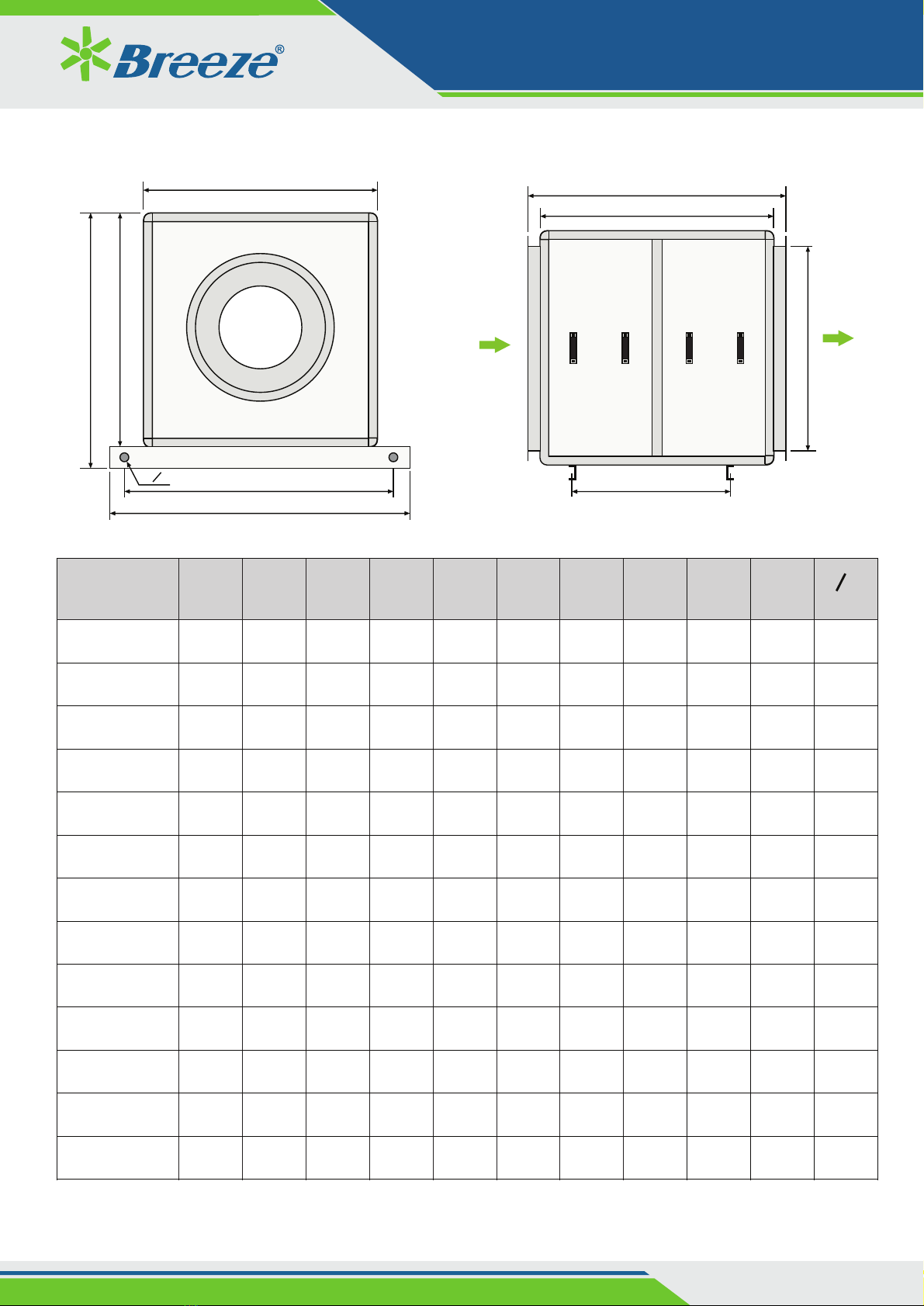
KBF/KBB Series: Inside Motor
All dimensions in mm.
Inlet Airflow
G1xG2
G3xG4
A
L
Model A B C D E G1 G2 G3 G4 L L1 Od
KB 200 960 990 625 50 690 256 256 453 568 600 850 15
KB 225 1000 1020 670 50 720 288 288 498 598 650 880 15
KB 250 1050 1050 710 50 750 322 322 538 628 680 910 15
KB 280 1120 1100 813 63 800 361 361 628 678 720 960 15
KB 315 1250 1270 878 63 970 404 404 673 828 850 1130 15
KB 355 1300 1350 953 63 1050 453 453 748 908 930 1210 15
KB 400 1480 1560 1130 80 1260 507 507 908 1118 1060 1420 15
KB 450 1550 1630 1220 80 1330 569 569 998 1188 1100 1470 15
KB 500 1600 1800 1310 80 1400 638 638 1258 1088 1160 1600 15
KB 560 1750 1850 1460 100 1450 715 715 1308 1218 1300 1650 18
KB 630 1880 2000 1590 100 1600 801 801 1458 1348 1320 1794 18
KB 710 2100 2200 1685 100 1800 898 898 1420 1635 1400 2000 18
KB 800 2280 2400 1855 100 2010 1007 1007 1848 1593 1600 2200 18
KB 900 2500 2600 2180 100 2210 1130 1130 2048 1793 1700 2400 18
KB 1000 2650 2750 2210 100 2360 1267 1267 2198 1948 1900 2550 18
D
8-Od
B
L1
C
E
4-O30
3. DIMENSION INFORMATION
* Dimensions shown are approximate only. The details please contact local sales office for more information.

04
www.breeze.com.vn | [email protected]
We bring better air to life
USER’S MANUAL
CDF/CDFS SERIES
B
L1 4-O30
8-O17
C
D
L
G1xG2
G3xG4
Airflow
Inlet
A
Model A B C D L L1 G1xG2 G3xG4
Y80 Y90 Y100 Y112 Y132 Y160 Y180 Y200 Y225
KB 200 610 790 860 540 498 690 256 428x328
KB 225 660 850 900 925 580 543 750 288 465x405
KB 250 710 910 940 960 630 593 810 322 525x455
KB 280 780 980 1020 1040 1070 703 663 880 361 595x515
KB 315 670 1060 1080 1100 1130 1160 1200 1295 763 420 960 404 655x555
KB 355 740 1160 1160 1180 1220 1250 1280 1380 1420 843 488 1060 453 755x635
KB 400 810 1260 1280 1300 1330 1380 1470 1520 930 513 1160 507 855x708
KB 450 890 1400 1360 1400 1430 1480 1570 1610 1660 1030 581 1300 569 978x808
KB 500 960 1520 1460 1500 1520 1570 1650 1700 1750 1120 650 1420 639 1095x895
KB 560 1060 1680 1600 1640 1660 1710 1800 1850 1900 1265 745 1580 715 1235x1020
KB 630 1160 1830 1760 1790 1830 1930 1970 2030 1390 846 1730 801 1385x1145
KB 710 1300 2020 1930 1970 2060 2110 2160 2210 1530 902 1920 898 1555x1265
KB 800 1430 2220 2140 2230 2270 2330 2380 1700 1030 2120 1007 1955x1435
KB 900 1610 2450 2290 2380 2425 2480 2535 1850 1166 2350 1130 1985x1585
KB 1000 1740 2700 2450 2540 2590 2640 2690 2010 1302 2600 1267 2235x1745
KBF-F/KBB-F Series: External Motor
* Dimensions shown are approximate only. The details please contact local sales office for more information.
All dimensions in mm.
04
www.breeze.com.vn | [email protected]
We bring better air to life
USER’S MANUAL
CDF/CDFS SERIES
Model A B C D EF G1 H L L1 Od
KBP 250 582 790 563 500 500 500 380 135 360 660 14
KBP 280 612 820 593 530 530 530 408 135 370 690 14
KBP 315 682 890 663 600 600 600 478 135 440 760 14
KBP 355 702 910 683 630 630 630 790 135 460 780 14
KBP 400 755 970 743 680 680 680 538 138 505 840 14
KBP 450 855 1080 860 780 780 780 638 155 590 940 14
KBP 500 975 1200 980 900 900 900 758 155 710 1060 14
KBP 560 1035 1260 1040 960 960 960 810 160 770 1120 14
KBP 630 1085 1310 1090 1010 1010 1010 868 160 810 1170 14
KBP 710 1205 1430 1230 1130 1130 1130 968 190 850 1290 14
KBP 800 1325 1550 1350 1250 1250 1250 1088 190 930 1410 14
KBP 900 1472 1700 1500 1400 1400 1400 1238 190 1060 1560 18
KBP 1000 1625 1850 1650 1550 1550 1550 1388 190 1150 1710 18
8-Od
C
D
B
L1
E
G1
L
A
F
Airflow
Inlet
KBP Series
* Dimensions shown are approximate only. The details please contact local sales office for more information.
All dimensions in mm.

We bring better air to life
USER’S MANUAL
FCS-FCD | BCS-BCD SERIES
08
4.1 Installation Guideliness
R
o
t
a
t
i
o
n
R
o
t
a
t
i
o
n
R
o
t
a
t
i
o
n
R
o
t
a
t
i
o
n
Once fan
impeller diameters
INCORRECT
Ducted Inlet Installations:
Ducted Outlet Installations:
Inlet Duct Turns - Installation of a duct turn or elbow too close to the fan inlet reduces fan performance because air is loaded
unevenly into the fan . To achieve full fan performance, there should be at least one fan diameters between the turn impeller impeller
or elbow and the fan inlet.
Discharge Duct Turns- Duct turns located near the fan discharge should always be in the direction of the fan rotation. Fan
performance is reduced when duct turns are made immediately o ffthe fan discharge. To achieve cataloged fan performance there
should be at least one equivalent duct diameters of straight ductwork between the fan discharge and any duct turns.
Length of Straight Duct
CORRECT
Turning
Vanes
CORRECT
INCORRECT
Inlet Spin - Inlet spin is a frequent cause of reduced fan performance. The change in fan performance is a function of the intensity of
spin and not easily defined. The best solution is proper duct design and airflow patterns. Turning vanes reduce the effects of inlet
spin.
CORRECT
Turning
Vanes
INCORRECT
01 fan
impeller
diameter
Single Fan Installation
Non-Ducted Installations:
Inlet Clearance - Installation of a fan with an open inlet too
close to a wall or bulkhead will cause reduced fan performance.
It is desirable to have a minimum of three-fourths of a impeller
diameter between the fan inlet and the wall.
Free Discharge - Free or abrupt discharge into a plenum
results in a reduction in fan performance. The effect of
discharge static regain is not realized.
4. INSTALLATION INSTRUCTION
•Move the fan to the desired location.
• Check and tighten fasteners throughout the unit and then fasten securely through mounting holes provided in the base angles.
• The unit must be set level (shimming may be necessary).
• Flexible duct connections and vibration isolators should be used where noise is a factor.
• The motor voltage and ampere rating must be checked for compatibility with the electrical supply prior to final electrical connection.
• Supply wiring to the fan must be properly fused, and conform to local and national electrical codes.
www.breeze.com.vn | [email protected]

We bring better air to life
USER’S MANUAL
FCS-FCD | BCS-BCD SERIES
09
www.breeze.com.vn | [email protected]
4.2 Guideliness for Noise Control
ŸEnsure transitions close to attenuators are
gradual or better still, remote.
ŸAbrupt transitions immediately adjacent to an
attenuator will cause the attenuator pressure
to increase.
Volume Control Dampers:
ŸAllow for a settling duct between volume
control dampers and attenuators.
ŸDon't site volume control dampers or fittings
too close to attenuators as they can cause a
dramatic increase in attenuator pressure
drop.
Attenuators in relation to bends:
ŸDo ensure attenuator splitters are in the
plane of the bend as shown. Fit turning
vanes it R/W<1.0
ŸDon't use attenuator splitters as shown when
sited close to a bend as the pressure loss
across it will be greater than expected.
Transitions: Ensure symmetrical transitions
from the duct equipment to fan inlet.
CORRECT INCORRECT
Volume control damper
CORRECT
Volume control damper
INCORRECT
CORRECT INCORRECT
ŸPlace a concrete sleeve around the silencer
to increase the acoustic seal between rooms.
For less stringent requirements, pack around
the silencer with a resilient material to affect
a complete seal between the attenuator and
the opening.
ŸWhen trying to achieve very high attenuation
or very low noise levels (e.g. NR20) do not
use an inadequate seal between the silencer
and wall opening.
Isolated walls:
ŸDo fix the silencer to one wall only and place
a flexible or resilient seal on the isolated wall.
ŸDon't bridge the isolated wall to the non-
isolated wall with the silencer fixings.
Acoustic sealing of silencers to achieve
low noise levels:
Flexible or
resillient seat
Isolated wall
Isolated wall
CORRECT
CORRECT
INCORRECT
INCORRECT

We bring better air to life
USER’S MANUAL
FCS-FCD | BCS-BCD SERIES
10
www.breeze.com.vn | [email protected]
Louvres on silencer discharge:
o
ŸDo ensure that the splitter orientation is at 90
to the louver orientation and place a spacer
between the silencer and discharge louver.
ŸDon't place a silencer immediately in front of a
louver.
CORRECT INCORRECT
ŸDo place a spacer between the louver and
the silencer and ensure that the splitter
o
orientation is at 90 to the louver orientation.
ŸDon't place a silencer immediately
downstream of a louver.
Fan positions relative to noise sensitive areas:
ŸBest: If fan cannot be relocated, wrap fan
and surrounding ductwork with a noise
barrier material (When wrapping fans pay
particular attention to ensuring there are no
holes at the joins). Allow sufficient overlap in
the wrap to ensure adequate coverage.
Remember that flexible connections will be
the weakest link.
ŸDo not place fans in ceiling spaces directly
above noise sensitive areas.
Flanking transmission:
ŸInstalling the attenuator through or against
the wall minimises the chance of flanking
transmission via the duct system ensuring
the expected performance is achieved.
ŸIf an attenuator is installed as shown, noise
from the fan can bypass the attenuator and
enter the conditioned space. This is known
as flanking transmission and will negatively
impact on the expected attenuator
performance.
Louvers on silencer inlet:
Better
Storeroom
Best
Better: Do place fans in ceiling spaces
away from noise sensitive areas
Overlap wrap by
100mm at all joins
Attenuator Attenuator
CORRECT INCORRECT
ŸDo use sweeping bends and take offs. Use
long chord turning vanes where possible.
Keep velocities low to reduce airflow
generated noise levels.
ŸDon't use sharp bends or take offs.
Changing direction of airflow:
ŸDo ensure velocities through supply and exhaust
grilled are low by increasing the grille size or
number of grilles. Size ductwork for constant static
pressure to each grille, thus eliminating or
minimissing the need for balancing damper
adjustment (which could / can generate excessive
noise).
ŸDon't allow high velocity air to pass through grilles.
When noise generated by grilles could
cause a problem:
CORRECT INCORRECT
CORRECT INCORRECT
CORRECT INCORRECT
CORRECT INCORRECT
Flanking
Transmission

05
www.breeze.com.vn | [email protected]
We bring better air to life
USER’S MANUAL
CDF/CDFS SERIES
4.3 Installation Method
Fig 01. Mounting type
Building Construction
Inlet Duct Airflow
Outlet Duct
Adjust Bolt
to reach
Spring Isolator
Flexible Connection
Fig 03. Hanging type
Building Construction
Airflow
Outlet Duct
Inlet Duct
Spring Isolator
FlexibleConnection
Steel Support
Stud
Building Construction
Spring Isolator
Fig 02. Hanging type
Stud
Steel Support
Ce manuel convient aux modèles suivants
30
Table des matières
Autres manuels Breeze Ventilateur


