Boyser DS-M Series Manuel utilisateur
www.boyser.com
Operating instruccions Peristaltic Pumps
DSM Series

2
Operating instruccions Peristaltic Pumps DSM Series
1. Introduction
This instruction manual must accompany the pump at all times for as long as it is in use.
The DSM series peristaltic pump is a machine for fluid handling intended to be used in
industrial areas, as such the instruction manual is part of the legislative provisions for the
safe and correct use of the pump.
This instruction manual does not substitute any installation standard or any additional
future standard.
1.1. How to use this manual
This manual is intended as a reference book by means of which qualified users are able
to install, commission and maintain the peristaltic pumps mentioned on the front cover.
1.2. Original instructions
The original instructions for this manual have been written in English. Other language
versions of this manual are a translation of the original instructions.
1.3. Other supplied documentation
Documentation of components such as motors and inverters is normally not included in
this manual. However, if additional documentation is supplied, you must follow the instruc-
tions in this additional documentation.
1.4. Service and support
For information with respect to specific adjustments, installation, maintenance or repair
jobs which fall beyond the scope of this manual, contact BOYSER. Make sure you have the
serial number peristaltic pump at hand.
1.5. Environment and disposal of waste
Enquire within your local government about the possibilities for reuse or environment
friendly processing of packaging materials, (contaminated) lubricant

3
2. Safety
2.1. Explanation of the safety information
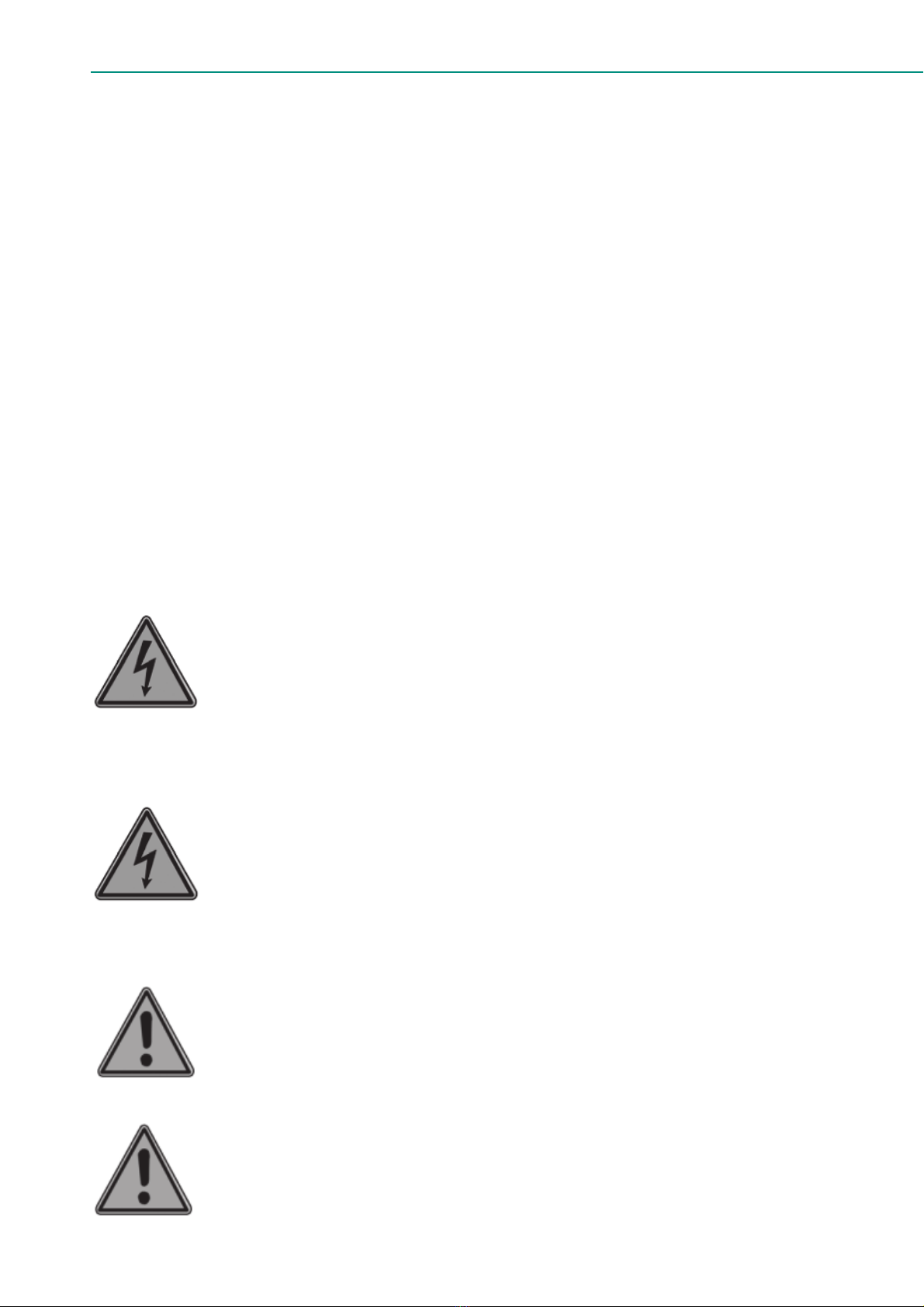
This symbol identifies the instructions of this manual, which must be
observed to avoid failure to meet safety standards.
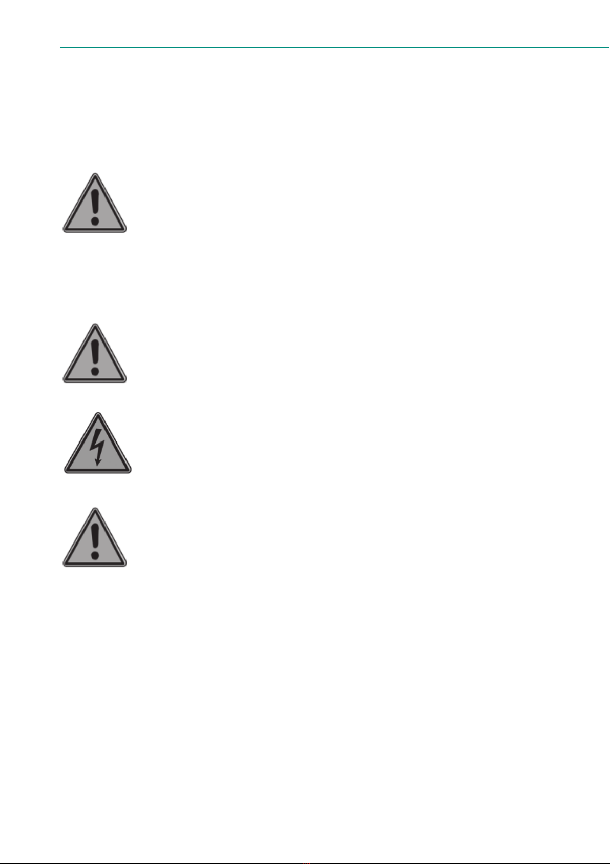
This symbol identifies the instructions of this manual, which must be
observed to avoid compromising electrical safety.
This symbol identifies the instructions of this manual, which must be
observed to guarantee the correct operation of the pump.
Other documentation supplied: instructions in all additional documentation supplied with
the pump must also be followed (instructions for components such as gearbox, motor,
sensor, frequency controller).
2.2. Intended use
The peristaltic pump is exclusively designed for pumping suitable products. Every other
or further use is not in conformance with the intended use. In case of doubt, it is the use
which appears to be its intended use judging from the construction, execution and func-
tion of the product. Observing the instructions in the user’s documentation also belongs
to intended use.
Only use the pump in conformance with the intended use described above. The manu-
facturer cannot be held responsible for damage or harm resulting from use that is not in
conformance with the intended use. If you want to change the application of your peris-
taltic pump, contact BOYSER.
2.3. Responsibility
The manufacturer does not accept any responsibility for damage or harm caused by not
(strictly) observing the safety regulations and instructions in this manual and the also su-
pplied documentation, or by negligence during installation, use, maintenance and repair
of the peristaltic pumps mentioned on the front cover. Depending on the specific working
conditions or accessories used, additional safety instructions can be required.
2.4. User qualifications
Pumps are machines that can present dangers due to moving parts and the presence of
a pressurised fluid within the tube.
4
Operating instruccions Peristaltic Pumps DSM Series
THE FOLLOWING CAN CAUSE SERIOUS DAMAGE AND INJURY:
- Improper use
- Removal of the protections and/or disconnection of protective devices
- Lack of inspections and maintenance
The person responsible for safety should therefore guarantee that the pump is transpor-
ted, installed, put in service, used, maintained and repaired by qualified personnel who
should possess:
- Specific training and sufficient experience for the tasks.
- Knowledge of the technical standards and applicable laws.
- Knowledge of the national and local safety and installation standards.
Any work carried out on the electrical part of the pump should be authorized by the per-
son responsible for safety.
Given that the pump is intended to form part of a system, it is the responsibility of whoever
supervises the installation of the entire system to guarantee absolute safety, adopting the
necessary measures of additional protection.
2.5. General safety information
Live parts
Possible consequence: fatal or very serious injuries.
- Risk mitigation: the device must be disconnected from the power
supply before it is opened
- Isolate damaged, faulty or manipulated devices from the mains in
order to de-energise.
Lack of emergency stop switch
Possible consequence: fatal or very serious injuries.
- An emergency stop switch must be connected for the entire system.
This should enable the entire system to be shut down in the event
of an emergency in such a way that the overall system can be brou-
ght into a safe condition.
Unauthorized access
Possible consequence: Fatal or very serious injuries.
- Risk mitigation: ensure that there can be no unauthorized access to
the pump or to the system.
Hazardous media/contamination of persons and equipment
Possible consequences: Fatal / serious injuries, material damage.
- Ensure that the tubes are chemically resistant against the media

5
being handled.
- Always observe the safety data sheets for the media to be handled.
The system operator must ensure that these safety data sheets are
available and that kept up-to-date.
- The safety data sheets for the fluid being handled are always deci-
sive for initiating countermeasures and/or first aid in the event of
leakage of the fluid.
- Observe the general restrictions in relation to viscosity limits, che-
mical resistance and density.
- Always switch the pump off before exchanging the tube.
Incorrect and improper use
Possible consequence: fatal or very serious injuries.
- The unit is not intended to convey or regulate gases or solid media.
- Do not exceed the rated pressure, speed or temperature for the
pump.
- Maximum pressure on suction/inlet side is 0,5 bar (7 psi approx.).
- The unit may only be used in accordance with the technical data
and specifications provided in these operating instructions and in
the operating instructions for the individual components.
- This pump is NOT supplied for use in areas of risk from explosion.
ATEX versions of BOYSER pumps are available and they are supplied
with a special ATEX version of the instruction manual.
- Only switch the pump on if it has been properly fastened to the
floor.
- Only switch the pump on if the front cover has been attached.
- Do not carry out any maintenance operations or dismantle the
pump without first making sure that the pipes are not under pres-
sure and are empty or isolated.
- In the case of the tube becoming stuck during extraction or fitting it
is necessary to reverse the direction of the pump, re-lubricate, and
then repeat the operation.
- As the peristaltic pump is volumetric and its functioning is positive
displacement, it is necessary to prevent a possible overload of pres-
sure, due to, for example, the accidental closure of a valve. For this
reason, it is advisable to fit a safety device such as: a safety valve,
pressure limiter, etc.
Operational lifetime of the tubes
Possible consequence: fatal or very serious injuries.
- The tube has an indeterminate life and due to the possibility of its
breakage or deterioration, the user is responsible for the preven-
6
Operating instruccions Peristaltic Pumps DSM Series
tion of a possible (although most unlikely) incorporation of particles
from the tube into the product being pumped. This can be achieved
by means of filtration, a tube rupture alarm or other means suitable
for the respective process
CIP cleaning
- In the event of CIP cleaning, it is necessary to obtain information
from the manufacturer about correct installation of the pump (a
special installation is required) as well as regarding the compati-
bility of the cleaning agents with the tubes and the hydraulic con-
nections.
- Cleaning should be undertaken at the recommended maximum
temperature.
Direction of rotation/flow direction
Possible consequence: material damage, destruction of the unit.
- The pump’s direction of rotation in relation to the desired flow di-
rection must be checked prior to every start.
Disconnect the pump from the mains
Possible consequence: personal injury.
- Work may only be carried out on the pump after it has previously
been switched off and disconnected from the mains.
Environmental influences
Possible consequence: material damage up to destruction of the unit.
- The device is suitable for outdoor operation once it is covered and
protected from rain and direct sunlight. Ambient conditions must
also be respected, see Section 6.2 & 6.3.
- Take suitable measures to protect the device from environmental
influences such as
- UV rays
- moisture
- frost, etc.

7
3. Functional description
The DSM Series is a positive displacement pump. The feed chemical is conveyed by the
rotor squeezing the tube in the direction of flow. No valves are needed for this. This ensu-
res gentle handling of the metered media.
Maximum pressure on suction/inlet side is 0,5 bar (7 psi approx.).
The DSM Series has been designed for safe and uncomplicated operation, as well as
straightforward maintenance.
The DSM Series can be used for many different media. However, this pump type is often
the optimal solution for abrasive, shear-sensitive and viscous media.
Typical areas of use include processes where only a low discharge pressure is required
(max. 2 bar).
3.1. Main modules:
1. Drive Unit
2. Housing
3. Base frame
DSM DSM LAB
1
2
3
1
2
3
8
Operating instruccions Peristaltic Pumps DSM Series
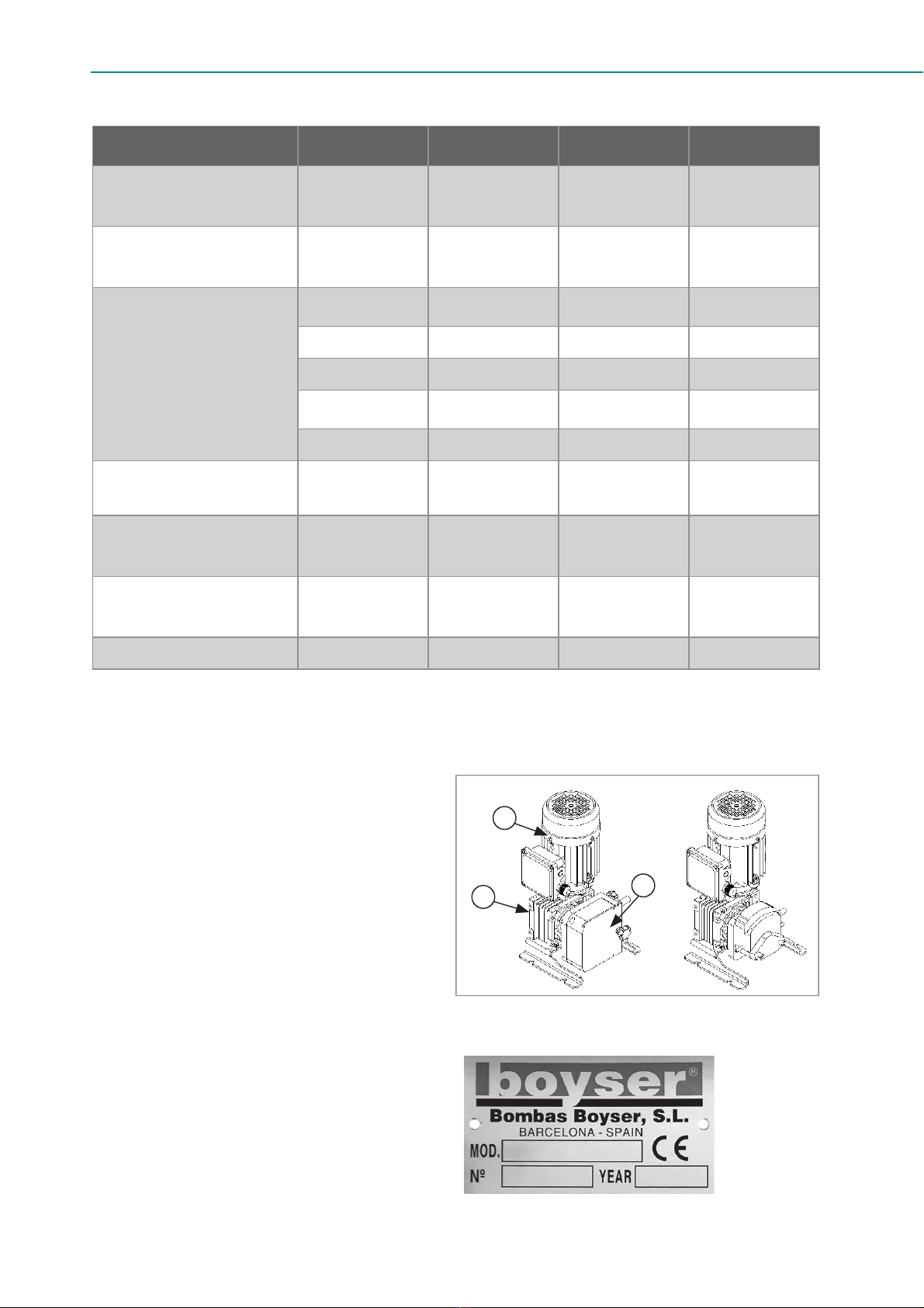
DESCRIPTION UNIT TUBE (Ø) DSM DSM/LAB
Max. capacity
continuous l/h -- 55,8 25,4
Max. capacity
intermittent l/h -- 84 38,2
Capacity per
revolution
ml/rev 1,6 mm 0,4 --
ml/rev 3,2 mm 1,65 0,75
ml/rev 4,8 mm 3,80 1,72
ml/rev 6,4 mm 5,61 2,54
ml/rev 8,0 mm 10,00 4,55
Max. permissable
working pressure bar -- 2 2
Permissable
ambient temperature °C -- -10 to +40 -10 to +40
Permissable
product temperature °C -- -10 to +80 -10 to +60
Sound level at 1m dB (A) -- 70 70
4. DESCRIPTION
4.1. Identification of the product
A: Pump head
B: Gearbox
C: Electric motor
4.2. Identification of the pump
MOD: Type number
Nº: Serial number
YEAR: Year of manufacture
DSM DSM LAB
A
B
C
9
4.3. Identification of the gearbox (B)
The gearbox has an identity plate with the model, serial number and manufacturer’s de-
tails as well as information relevant to its function such as reduction ratio.
4.4. Identification of the electric motor (C)
The motor has an identity plate with the model, serial number and manufacturer’s details
as well as information relevant to its’ function such as electric power.
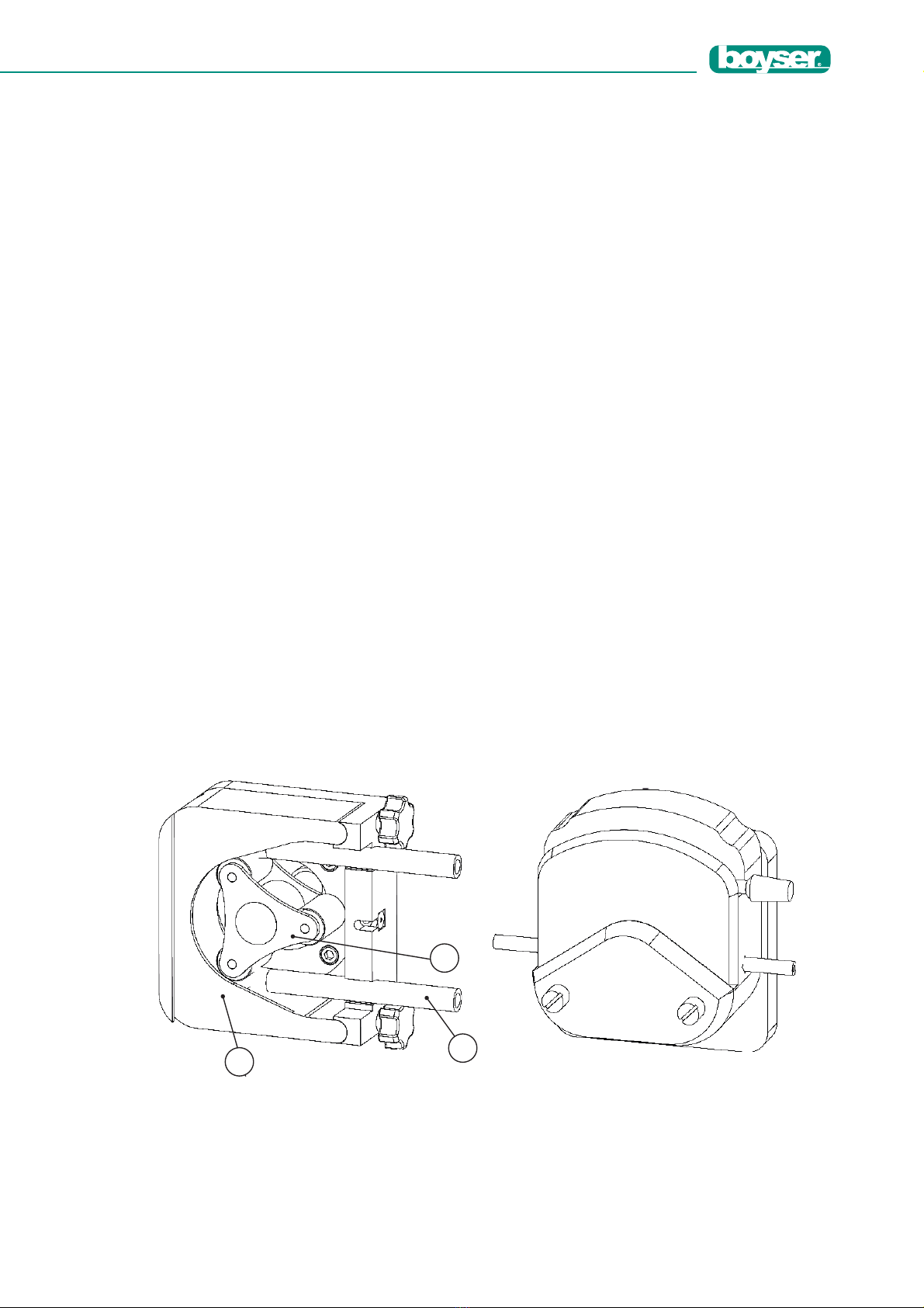
5. CONSTRUCTION
The pump housing is closed off with a bolted front cover in order to avoid the risk of injury.
The motor serves to drive the rotor. Two shoes attached to the rotor serve to press the
tube against the pump housing.
The rotary movement of the rotor alternately presses and releases the shoes against the
tube. This serves to suck the media and convey it into the metering line.
5.1. Diagram of functional principle
1. Housing
2. Rotor
3. Tube
DSM DSM LAB
13
2

10
Operating instruccions Peristaltic Pumps DSM Series
6. TRANSPORT AND STORAGE
6.1. Transport
- The pump is protected by cardboard packaging or a wooden crate.
- The packaging materials are recyclable.
6.2. Storage for less than 1 month
- The pump should be in a resting position, rotor in horizontal position.
- Avoid areas open to harsh weather or excessive humidity and temperatures lower
than 0°C or higher than 30°C.
- Spare tubes should be stored in a dry place away from direct light.
6.3. Storage for more than 1 month
- Avoid areas open to harsh weather or excessive humidity and temperatures lower
than 0°C or higher than 30°C.
- IMPORTANT Disassemble the tube from the housing (see section 8.2).
- For storage periods of longer than 30 days, protect the coupling surfaces (clamps,
reducers, motors) with adequate anti-rust protection.
- For storage periods longer than 6 months, rotate the rotor a few turns to prevent
damage to bearings and oil seals and to prevent grease migration.
- Spare tubes should be stored in a dry place away from direct light.
6.4. Elevation
- DSM pumps sizes can be lifted manually.
- It is the customer’s responsibility to adhere to local workplace legislation.
Weights DSM DSM/LAB
Total pump weight <11 kg <11 kg
<24,25 lbs <24,25 lbs
Lifting 1 person 1 person
Autres manuels pour DS-M Series
1
Ce manuel convient aux modèles suivants
2
Table des matières
Autres manuels Boyser Pompe à eau


Manuels Pompe à eau populaires d'autres marques


Sykes AmeriPumps
Sykes AmeriPumps GP100M Guide de dépannage

DUROMAX
DUROMAX XP WX Series Manuel utilisateur

BRINKMANN PUMPS
BRINKMANN PUMPS SBF550 Manuel utilisateur

Franklin Electric
Franklin Electric IPS Manuel utilisateur

Xylem
Xylem e-1532 Series Manuel utilisateur

Milton Roy
Milton Roy PRIMEROYAL Manuel utilisateur