BotKits.com D2 COMBAT ROBOT KIT Manuel utilisateur

D2 Combat Robot Chassis Kit Instructions

Parts included in kit:
Part
D2-Side[B]
Count
2
D2-End[A] 2
D2-Bottom[A] 1
D2-Top[B] 1
D2-Wed
g
eTi[B] 1
D2-WedgeBracket-L[C] 1
D2-Wed
g
eBracket-R[C] 1
D2-WedgeMount[-] 1
D2-MotorBrace[A]
(
3
)
& D2-SwitchMount [-]
(
1
)
1
M3 x 6mm Flat Head Screws (Top & Bottom - pack of 20) 1
10-24 x 3/4” Socket Head Screws
(
Ends - pack of 8
)
1
RP-01-005-Kit[C] Axle Adapter Kit 4
#6 x 5/8” Sheet Metal Screws
(
Motor braces - pack of 8
)
1
M3 x 10mm Flat Head Screws
(
Wed
g
e - pack of 20
)
1
1/4-20 x 3/4” Socket Head Screws (Wedge - pack of 2) 1
1/4-20 x 7/8” Socket Head Screws
(
Wed
g
e - pack of 2
)
1
1/4-20 Lock Nuts (Wedge - pack of 2) 1
RP-GM-22-12V780 DC Gear Moto
r
4
Soft Foam Wheel 4
Mini Power Switch & Hex wrench
(
pack
)
1
LED Power Indicator Light 1
4” Velcro Strip 1
D2 Wire set 6” (5 Red & 5 Black)
Hex wrench
(
2mm
)
1
1
Additional Parts Required:
Speed control (we recommend the Robot Power Scorpion Mini available in our store)
Radio (we use the Spektrum DX4C)
Battery (we use the Turnigy Graphene 500mAh 4S 65C Lipo Pack)
Battery plug for the primary leads plug on your selected battery
Foam sheet or bubble wrap to secure battery
Battery charger appropriate for your selected battery
Tools Required:
Standard hex wrenches
Cross head screwdriver
7/16” open end or adjustable wrench
Wire stripper
Soldering iron and solder
CAUTION: THIS ROBOT IS POWERFUL AND FAST! MAKE
SURE YOU ONLY OPERATE THE ROBOT IN AN AREA
WHERE IT CAN NOT CAUSE DAMAGE OR INJURY!

Assembly:
Step 1 – Temporary assembly:
Form the basic chassis by assembling the 2 sides, 2 ends, 4 motors, and bottom plate:
Use 4 of the 10-24 x 0.75 socket head cap screws in the lower holes on each end to very
loosely (e.g. floppily) connect the ends to the sides. There is no up/down/left/right. All
of the sides and ends can be used in any position (the large hollowed out areas go towards
the insides).
Slide the motors into the motor bores until just the black head of the motor (where the
shaft comes out) is extending beyond the side of the robot.
Snug (e.g., finger tight) the 4 screws so the motors are temporarily held in place.
Attach the aluminum bottom plate to the chassis using 2 of the M3x0.5 machine screws
and the included hex wrench.
Step 2 – Arrange Electronics:
Arrange your battery, receiver, and speed controller on the bottom plate, as you expect to
place them in the finished robot.
The battery is in there just to make sure sufficient room is being left for it.
Make sure there is sufficient clearance between everything and the motors, allowing for
spacing up of the receiver and speed control when they are attached using servo tape
(etc.).
Mark the location of your receiver and speed controller on the bottom plate.
Step 4 – Attach Electronics:
Remove the bottom plate and attach your receiver and speed controller using the included
Velcro strips.
Step 5 – Wiring Preparation:
Determine wire lengths needed to connect your motors to your speed control and from the
battery to the switch and speed control:
Loosely attach the bottom plate.
Measure from the motor solder lugs to the speed control lugs.
Place the battery in the chassis, and determine wire lengths needed to connect to the
power switch (positive lead) and the speed control (negative lead).
At the same time, trim the power LED leads to an appropriate length to connect to the
power lugs on the speed control.

Step 6 - Wiring:
Disassemble the entire chassis.
Cut the included wires and LED wires to the lengths determined in the previous step.
Strip the ends of the wires.
Pre-tin the wire ends, switch lugs, and motor lugs. IMPORTANT: Do NOT use silver
solder.
Carefully and quickly solder wire pairs to the motor lugs. Too much heat on the motor
lugs will cause premature motor failure.
Solder main power positive wires to the power switch. Attach the other end to the
positive terminal of an appropriate plug for your selected battery.
Solder main power negative wire to the negative terminal of the battery plug. Attach the
other end to the speed control.

Step 7 - Assemble the robot:
Slip the white plastic motor braces over the motor wires and on to the motor bodies.
Attach the plastic motor braces and motors with the included #6x5/8” sheet metal screws.
Insert the motors, up to the heads, being sure to have the motors with the appropriate wire
lengths in the correct locations. The motor brace with the added slot for the power switch
should be in the rear-left position.

Snug the bottom screws, add the upper set of 10-24 machine screws, then tighten the
upper screws. This will result in the lower screws becoming tight, as we achieve a
compression fit around the motor gearbox.
Attach the lower plate, using 8 of the supplied M3 x 6mm machine screws.
Connect the motor leads to the speed control. Both wire sets from one side of the robot
will attach to one of the speed control ports, and the other side to the other port. Note the
polarity will be reversed, one side to the other.
Connect the main power leads and the power LED leads to the speed control power lugs.
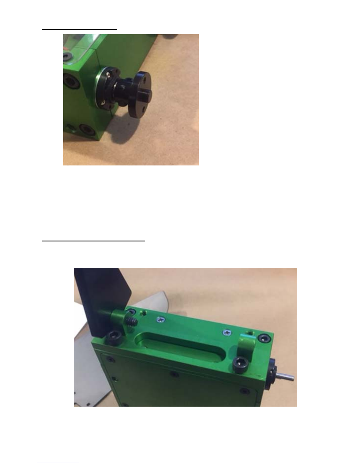
Step 8 - Attach wheels:
Loosely screw the supplied 4-40 machine screws into the axle clamp portion of the axle
adapters.
Slide each axle adapter fully onto a motor shaft, with the clamp portion towards the
chassis, and tighten the 4-40 machine screws to secure the adapters to the motor shafts.
Slide a wheel onto each of the axle adapters, and secure with the supplied 6-32 machine
screws. Your 4-40 sized Allen wrench can be used to help align the holes in the wheel
hub with the tapped holes in the axle adapters.
Step 9 - Attach titanium wedge:
Attach wedge mount piece to lower end with included ¼-20 x ¾” socket head screws.
It should be flush with the bottom edge of the bot.
Finger tighten included ¼-20 x 5/8” screws through wedge brackets through the
mount on both sides. Make sure the appropriate side bracket is on the correct side.
Leave screws somewhat loose to allow free movement and alignment with wedge.

Using a wrench, secure lock nuts on inside of screws. Tighten securely against wedge
mount, but make sure brackets stay somewhat loose.
Attach titanium wedge to brackets with 16 M3 x 10mm flat head screws.

Step 10 - Power on test:
CAUTION: THIS ROBOT IS POWERFUL AND FAST!
MAKE SURE YOU ONLY OPERATE THE ROBOT IN AN
AREA WHERE IT CAN NOT CAUSE DAMAGE OR INJURY!
Make sure the robot power switch is off.
Attach the battery and secure it in the chassis by wrapping it with an appropriate
amount of foam sheet or bubble wrap to take up excess space in the chassis around
the battery.
If you have not yet bound your radio to the receiver, do that now, following the
instructions provided with your radio.
Attach the clear plastic top cover using the 8 supplied M3 x 6mm machine screws.
The plastic top will allow your radio to reach the receiver without having the antenna
outside of the robot. Make sure the mini power switch aligns with the hole in the
plastic cover.
Turn on your radio and the robot, and test movement. There is no front or back on
the robot until you attach a weapon. If you have a preferred front (e.g., we like to
have the battery at the “front” of the robot), and the robot is going backwards to the
input you give on the radio, power down the robot and reverse the motor power leads
on the speed control.

Hints and Tips:
Grind the lower edge of the wedge:
Takes time, but will help your wedge get under other bots more easily. Belt sander is the
easiest way to do this.
Swap a motor:
You do not have to fully disassemble the robot to change a motor:
Remove the top cover
Disconnect the leads from the speed control for the affected motor.
Loosen the M3 screws on the bottom that screw into the end with the bad motor
Loosen the 10-24 screws on the end with the bad motor.
Slide out the bad motor
Move the leads to a good motor, slide it back in, tighten up, attach the axle adapter
and wheel, and you are ready to go!
Have a suggestion? Contact us via http://www.botkits.com
Autres manuels pour D2 COMBAT ROBOT KIT
1
Table des matières
Autres manuels BotKits.com Robotique

Manuels Robotique populaires d'autres marques

STEMCenter USA
STEMCenter USA Pi-Bot v2.00 Manuel utilisateur

SunFounder
SunFounder PiDog Manuel utilisateur

Universal Robots
Universal Robots UR5 Manuel utilisateur

Universal Robots
Universal Robots E Series Manuel utilisateur

YASKAWA
YASKAWA MOTOMAN-MPL80 II Manuel utilisateur

EFORT
EFORT ECR5 Manuel d'instructions


