BOSSCO SY-200 Manuel utilisateur

2
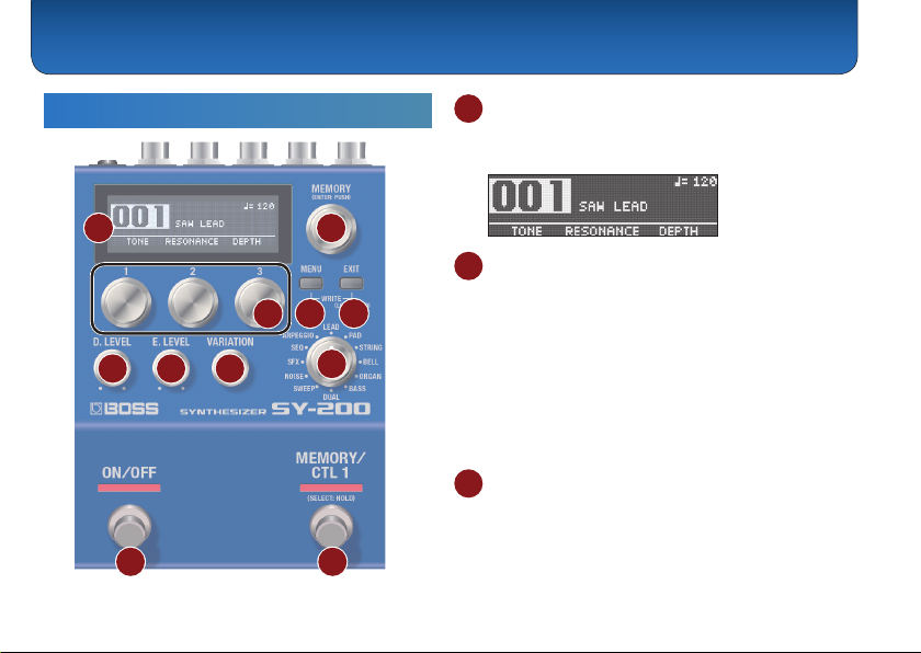
Panel Descriptions
Top Panel
1 2
3 4 5
6 7 8 9
10 11
1 Display
Displays various information such as the current
memory number.
2 [MEMORY] knob
MEMORY (turn the knob)
Turn the knob to switch between memories 1–128
(p. 7).
To change a value in larger steps, turn a knob while
pressing it.
ENTER (press the knob)
Press this knob to conrm the setting or perform other
tasks.
3 [1]–[3] knobs
Use these knobs to set the parameter values shown in
the screen.
To change a value in larger steps, turn a knob while
pressing it.

Panel Descriptions
3
4 [MENU] button
The menu screen appears.
5 [EXIT] button
Returns you to the previous screen. In some screens,
this cancels the function currently being executed.
Preventing accidental operation (panel lock)
By holding down the [EXIT] button, you can switch
between enabling (unlocking) or disabling (locking) the
knobs and buttons.
If you use these controls while the unit is locked, the
display indicates “LOCKED.”
MEMO
Press both the [MENU] and [EXIT] buttons together to
display the WRITE UTILITY screen, where you can save,
exchange and initialize the memories (p. 7).
6 [D. LEVEL] knob
This adjusts the volume of the direct sound.
7 [E. LEVEL] knob
This adjusts the volume of the eect sound (synth
sound).
8 [VARIATION] knob
This selects variations for the type that is selected.
9 Type knob
Use this knob to switch between dierent synth sound
types.
Type Explanation
LEAD Suitable for playing solos or leads
PAD Soft sounds used as sonic ll-ins
STRING Synth strings sounds
BELL Sounds with metallic resonance
ORGAN Organ sounds
BASS Bass synth sounds
DUAL Fat sounds
SWEEP Sounds with a characteristic vibration
NOISE Noise sounds
SFX Sound eects and distinctive sounds
SEQ Sounds whose pitch or character changes
rhythmically
ARPEGGIO Arpeggio phrases that play

Panel Descriptions
4
10 [ON/OFF] switch
Turns the eect (synth sound) on/o.
11 [MEMORY/CTL 1] switch
Switches between memories (p. 7).
Holding this down makes it function as the [CTL 1]
switch.
MEMO
You can change the footswitch function with the
“FUNCTION” (ON/OFF FUNCTION/CTL FUNCTION) parameter.
Rear Panel
* To prevent malfunction and equipment failure, always turn down the
volume, and turn o all the units before making any connections.
A B C D E
F
A INPUT jack
Connect your guitar, bass, or eect unit here.
Turning on/o the power
The INPUT jack also serves as the power switch. The
power turns on when you insert a plug into the INPUT
jack.

Panel Descriptions
5
* Once everything is properly connected (p. 4), be sure to follow the
procedure below to turn on their power. If you turn on equipment in
the wrong order, you risk causing malfunction or equipment failure.
* Before turning the unit on/o, always be sure to turn the volume down.
Even with the volume turned down, you might hear some sound when
switching the unit on/o. However, this is normal and does not indicate
a malfunction.
When powering up
Turn on equipment such as your guitar amp last.
When powering down
Turn o equipment such as your guitar amp rst.
B SEND/RETURN jacks
This unit sends signals from the SEND jack to an
external eect unit, and receives signals from an
external eect unit via the RETURN jack.
You can switch the SEND/RETURN function using
the “SEND/RETURN” parameter.
C OUTPUT jack
Connect this jack to your amp or monitor speakers.
D CTL 2, 3/EXP jack
Using the jack as CTL 2/3
You can connect a footswitch (sold separately: FS-5U,
FS-6 or FS-7) and assign it to control a variety of
functions (p. 9).
Using the jack as EXP
You can connect an expression pedal (EV-30, Roland
EV-5 or similar, sold separately) and use it to control the
volume or tonal character of the synth sound (p. 12).
* Use only the specied expression pedal. By connecting any other
expression pedals, you risk causing malfunction and/or damage
to the unit.
E DC IN jack
Use this jack to connect an AC adaptor (PSA-S series,
sold separately).
* Use only the specied AC adaptor (sold separately: PSA-S series)
and plug it into an AC outlet of the correct voltage.
* If the AC adaptor is connected while the batteries are installed, the
power supply is drawn from the AC adaptor.
F Ground terminal
* Connect this to an external earth or ground if necessary.

Panel Descriptions
6
Side Panel
G H
G MIDI jacks
Use a TRS/MIDI connecting cable (BMIDI-5-35, sold
separately) to connect an external MIDI device. You
can use an external MIDI device to switch between
memories on this unit.
* Do not connect an audio device here. Doing so will cause
malfunctions.
H USB port
Connect your computer using a commercially available
USB cable that supports USB 2.0.
* Do not use a micro USB cable that is designed only for charging a
device. Charge-only cables cannot transmit data.
* Used only for updating programs.

7
Saving to a Memory
You can save the settings you’ve edited.
1. Press the [MENU] and [EXIT] buttons at the
same time.
The WRITE UTILITY screen appears.
2. Use the [1] knob to select “WRITE.”
3. Use the [1] knob to select the memory (1–128)
to which you will save the settings, and press
the [MEMORY] knob.
You can also edit the name here.
Controller Operation
[1] knob Edits the character.
[2] knob Moves the cursor.
[3] knob Changes the character type.
[MENU] button Delete one character
4. Press the [MEMORY] knob.
The current settings are saved.
Switching Between Memories
Here’s how to recall a saved memory.
1. Turn the [MEMORY] knob.
The memory number changes in ascending order (1
02 03 04... 128).
MEMO
5Hold down the [MEMORY] knob to switch between screen
displays.
Memory number displayed larger
Memory name displayed larger
5Turn the [MEMORY] knob to move the cursor and edit the
tempo.
Saving and Switching Between Memories

Saving and Switching Between Memories
8
Exchanging Memories
You can change the order of saved memories by
exchanging them.
1. Turn the [MEMORY] knob to select the memory
to exchange.
2. Press the [MENU] and [EXIT] buttons at the
same time.
The WRITE UTILITY screen appears.
3. Press the [2] knob and select “EXCHANGE.”
4. Turn the [1] knob to select the memory to
exchange.
5. Press the [MEMORY] knob.
This exchanges the memories you selected in steps
1 and 4.
Initializing a Memory
You can return (initialize) a memory to its standard
settings. This is useful when you want to create a new
tone from scratch.
1. Turn the [MEMORY] knob to select the memory
to initialize.
2. Press the [MENU] and [EXIT] buttons at the
same time.
The WRITE UTILITY screen appears.
3. Use the [3] knob to select “INITIALIZE.”
The memory is initialized.

9
Various Settings (Menu)
Basic Operations
1. Press the [MENU] button.
The unit enters MENU mode.
2. Press knobs [1], [2] and [3] to select the item
to edit.
Hold down the [MEMORY] knob to switch between
the setting pages.
3. Use the [1], [2], [3] and [MEMORY] knobs to edit
the settings for each item.
4. When editing parameters besides“SYSTEM”
(p. 13),“MIDI” (p. 13), and“MIDI PC MAP”
(p. 14), operate the unit as shown in “Saving
to a Memory”(p. 7).
* If you do not do this, the changes are lost when you switch memories.
5. Press the [EXIT] button.
The unit exits MENU mode.
Assigning functions to an external pedal
You can connect a footswitch (FS-5U, FS-6 or FS-7, sold separately)
to the CTL 2, 3/EXP jack, and use it to tap-input the tempo or to
switch memories.
The settings for this are in the“CTL FUNCTION,” found in the menu
(p. 10).
FS-5U FS-6/FS-7
CTL 3 CTL 2 CTL 3 CTL 2
CTL 3
CTL 2
CTL 2
FS-5U × 2
FS-5U FS-6/FS-7

Various Settings (Menu)
10
Parameter List
ON/OFF FUNCTION
These parameters specify the function of the [ON/OFF]
switch.
Parameter Value
FUNCTION
Sets the function of the switch.
5ON/OFF: Eect on/o
5MEMORY: Switches between
memories.
5MEM/ON: Switches between
memories. Hold down the switch to
switch to the eect on/o function.
Parameter Value
PARAM
Sets how the switch operates.
ON/OFF:
5TOGGLE: Switches the eect with each
press of the switch.
5MOMENT: Switches the eect only
while the switch is pressed.
MEMORY:
5INC: Increments the memory number
according to the MEMORY EXTENT
MIN/MAX setting.
5DEC: Decrements the memory number
according to the MEMORY EXTENT
MIN/MAX setting.
51–128: Switches to the specied
memory.
PREF
5MEMORY: Changes the settings per
memory.
5SYSTEM: Makes the settings the same
for all memories.
CTL FUNCTION
Use this to congure the functions of the
[MEMORY/CTL 1] switch and the footswitch connected
to the CTL 2, 3/EXP jack.
Table des matières
Autres manuels BOSSCO Synthétiseur

BOSSCO
BOSSCO SY-300 Mode d’emploi

BOSSCO
BOSSCO DR-5 Dr. Rhythm Section Manuel utilisateur

BOSSCO
BOSSCO SY-1000 Manuel utilisateur

BOSSCO
BOSSCO DR-202 Dr. Groove Manuel utilisateur

BOSSCO
BOSSCO SY-1000 Manuel utilisateur

BOSSCO
BOSSCO SYB-5 Manuel utilisateur

BOSSCO
BOSSCO GM-800 Manuel utilisateur

BOSSCO
BOSSCO GM-800 Manuel utilisateur


