
BOSSCO BOL5 Guide de démarrage rapide

Installation Instructions
and
Owner’s Manual
READ THIS MANUAL CAREFULLY BEFORE BEGINNING INSTALLATION
Installer: Permanently attach manual to the wall.
Model BOL5/BOL6
1
Read and Follow These Important Safety Instructions
You will see Warning and Caution statements on the following Pages.
Read and follow these safety instructions carefully. Failure to do so could result in serious personal injury or death.
Warning means that severe injury or death may result from failure to follow instructions
Caution means that property damage or injury may result from failure to follow instructions
•
• Be sure to read and follow all instructions carefully.
• To reduce the risk of electric shock, this equipment has a grounding type plug, that has a third (grounding) pin.
This plug will only fit into a grounding type outlet. If the Plug does not fit into the outlet, contact a qualified
electrician to install the proper outlet. Do not change the plug in any way.
• Check to make sure the garage door is properly installed and balanced. Garage door & parts are under
extreme tension and under no circumstance should you attempt to adjust on your own. Have a qualified
garage door service person make repairs to cables, spring and other hardware before installing the opener.
• Install Entrapment Warning Label next to control button. Read the Control Adjustment Warning Label. Install
Emergency Release Tag to the Emergency Release Cord. Mount the Emergency Release Knob 180cm from the
floor. Use the manual release only to disengage the trolley. Do not use the Red Release Cord and Knob to pull
door up or down. If possible, use the Emergency Release only when the door is closed.
• Do not connect opener to power source until instructed. Install door opener 210cm or more above floor.
• After installing opener, the door must reverse when it comes in contact with a 5cm high object. Check this safety
feature often.
• REMOVE ALL ROPES CONNECTED TO THE GARAGE DOOR.
• DISENGAGE ALL EXISTING GARAGE DOOR LOCKS TO AVOID DAMAGE TO THE GARAGE DOOR.
• Fiberglass, aluminum and steel doors must be reinforced to prevent damage. Consult with manufacturer for
recommendations.
• All installation and wiring must be done in strict compliance with local and state building and electrical codes.
Connect the power cord to a properly grounded outlet only. Do not in any way alter or remove the grounding pin.
Photo Eye System must be installed properly. Boss Operators recommend Photo Eye System is installed on
every garage door for your added protection. Opening doors must not close and Closing doors must open. See
test procedure page 13 and page 16.
• Locate push button within sight of garage door, away from all moving parts and out of reach of children (minimum
150cm above floor). To reduce the risk of injury to persons, use this operator only with a sectional door.
• Never operate the opener if the system is not operating properly.
• Always disconnect electric power before making repairs or removing cover.
• Activate opener only when the door is in full view and free from obstructions.
• No one should enter or leave the garage while the door is moving. Do not allow children to play near, or operate
the door. Keep the remote control away from children.
• After Installation is complete fasten this manual near the garage door. Perform periodic safety checks and
recommended maintenance and adjustments.
• NEVER GO UNDER A STOPPED, PARTIALLY OPEN DOOR.
• Test door opener monthly. The garage door MUST reverse on contact with a 5cm high object (or a two by 4
board laid flat) on the floor. After adjusting either the force or the limit of travel, retest the door opener. Failure to
adjust the opener properly increases the risk of severe injury or death.
• For products having an emergency release, when possible, use the emergency release only when the door is
closed. Use caution when using this release with the door open. Weak or broken springs are capable of
increasing the rate of door closure and increasing the risk of severe injury or death.
• KEEP GARAGE DOORS PROPERLY BALANCED. See owner’s manual. An improperly balanced door increases
the risk of severe injury or death. Have a qualified service person make repairs to cables, spring assemblies, and
other hardware.
• Coach Screws are supplied with the door for fitting to timber. Correct and safe fastening to other materials may
require different fasteners. The install must select and use fasteners appropriate to the material into which they
are being fixed.
• NOTE– IT IS THE INSTALLER’S RESPONSIBILITY TO ENSURE THAT THE FIXING METHODS ARE SOUND
!

Product Features
1. Motor: Permanently Lubricated, thermally protected, heavy duty motor with Automatic reset.
2. Opener Lights: Turn on and off automatically with 2.5 minutes illumination for your safety and convenience.
3. Sensing System: A built-in sensing system detects obstructions during door operation. If in the Downward (close)
travel mode, the Opener will sense an obstruction and reverse to the full open position. In the Open mode, the
Opener will stop. In both cases the operator will beep continuously for 20 seconds. Since all doors are different, the
Sensing System has independent adjustments for customizing the level of force for the normal opening and closing of
specific door.
4. Close Limit Switch: In winter months it’s common for small pieces of ice or packed snow to be trapped under the
door. Ground swelling may also effect the close limit setting of the Opener. The Close Limit Switch overrides the
Sensing System under the last one (5) cm of closing travel and prevents the door from reversing if it encounters an
obstruction at this point. When the Light flashes at the doors closed position, it’s about time to shovel the snow or re-
adjust the close limit higher.
5. Emergency Release: A pull cord allows manual disconnect and operation of door during power failure. Unit will
automatically reconnect when release is reset (the trolley release lever is snapped back to its original position), power
is restored and Opener is activated.
6. Mechanical Door Lock: When properly adjusted, opener locks door in closed position preventing unwanted entry.
7. Easy Connect Continuous Monitor Entrapment System: System allows quick and easy installation of “Silent Guard”
Photo Eye System while control circuitry monitors these devices continuously for proper operation.
8. Constant Contact to Close: For utmost safety if “Silent Guard” Photo eye system fails constant contact of mechanical
push button is necessary to close door. In this mode of operation, a radio transmitter cannot be used to close door.
9. Momentary Contact to Close: Single touch to Radio Transmitter or Wall Button will allow door to close as long as
Silent Guard Photo eye system is operational.
10. Silent Guard Photo Eye System: An invisible infra-red beam of light guards the door opening and reverses a
downward moving door if the beam is broken by a stationary or moving object. If the beam is broken, the opener will
beep for 20 seconds. Motor control circuitry constantly monitors the Photo Eye System for proper operation.
11. Digital Radio Control: Built in allowing over 1.6 million private codes, easily selected without use of tools. Bright
transmitter LED indicates operation and monitors battery condition.
12. Auto Force Learning: After setting the Up Limit and Down Limit is complete the door will run once from the Up Limit to
the Down Limit the data from this is stored in the memory. The red and green LED turn off and the opener beeps 3x,
the learning is then complete.
13. Soft Open/Close: The door soft open/close for a distance of 20-30cm depending on the size of the door being lifted.
14. Security Switch: When the Security Switch is activated the Door will not be able to operate. Signal from the Wall Box,
Transmitter, Push Button, and Up/Down button are all ignored. Light button will continue to function normally.
2

1. Raise and lower the door and check closely for areas of
sticking and binding. Check for loose hinges, wobbly
rollers, frayed cables and damaged or broken springs.
Contact a qualified garage door service person to make
the necessary adjustments.
2. Lift the door approximately halfway. When released,
the door should stay in that position. If door pulls open
or moves downward, the spring mechanism is not
adjusted properly. Contact a qualified garage door
service person to make the necessary adjustments.
3. When properly installed and adjusted the door will
remain clear of the opening, when allowed to rest at its
natural full open position. If door drifts up or down the
door is not adjusted properly. Contact a qualified
garage door service person to make the necessary
adjustments.
Door Test
Before beginning installation of the operator please complete the following test to insure that your door is balanced and in
good working condition. A poorly balanced door could cause severe personal injury and damage to the opener.
Always have a qualified garage door service person make any needed adjustments and/or repairs to your door before
proceeding with installation.
Do not install the opener until these adjustments and repairs have been made.
Sectional Door
! Carefully follow the instructions for the assembly and installation of the garage door opener
contained in this manual
Tools Required for Assembly and Installation
Level
Tape
Measure
Hand Saw Step Ladder
1/2” and 7/16”
Socket and
Wrench
Pencil
3/16” and
5/16” Drill
Drill
Pliers
Open End
Wrench
5/16” and
1/4”
Claw Hammer
3
Screw Driver

(01) Hex Bolt 5/16”18x1 (4 pcs)
(02) Lag Screw #12x1” (6 pcs)
(03) Hitch Pin (3 pcs)
(04) Flange Nut 1/4”-20 (4 pcs)
(05) Flange Nut 5/16”-18 (4 pcs)
(06) Clevis Pin Long (1 pcs)
(07) Clevis Pin Short (2pcs)
(08) Rope Knob (1 pcs)
(09) Rope (1 pcs)
(10)Washer(2 pcs)
(11)5W lamp
(3)
(2)
(1)
Components Identification and Inventory
Fastener (parts in screw bag) Identification
(4)
(5)
(6) (7)
(8)
(9)
(1)
(2)
(3)
(4)
(5)
(6)
(7)
(01) Power Head
(02) Header Bracket
(03) Door Bracket
(04) Door Arm: Straight
(05) Door Arm: Curved
(06) Warning Label
(07) Rail Assembly
(08) Trolley
4
(10)
(8)
(11)

01
Assembly 01
STEP 1.
Remove packing materials.
STEP 2.
Insert trolley (see fig.2).
STEP 3.
Connect rail to power head. Align rail and power head and
slide rail over drive shaft & retaining lugs. Fasten with 4
nuts.
Coach Screws are supplied with the door for fitting to
timber. Correct and safe fastening to other materials may
require different fasteners. The installer must select and
use fasteners appropriate to the material into which they
are being fixed.
NOTE: IT IS THE INSTALLER’S RESPONSIBILITY TO
ENSURE THAT THE FIXING METHODS ARE SOUND
STEP 4.
Adjust the tension of belt at end rail. Turn clockwise to
tighten and counterclockwise to loosen.
NOTE: improper tension will result in abnormal opener
operation.” (3-4 turns clockwise is recommended)
5
02
1
2
04
Tighten
Loosen
03
2 . 1/4” -20Hex Flange
Nuts (4)
1

#12x1"Lag Screw
Pre-Drawn
Vertical Line
1/2 Door Frame
1/2 Door Frame
Pre-Drawn
Horizontal
Header Bracket
05
Assembly 02
06
STEP 5.
Install head bracket. The height is seen in fig.5 Head
bracket position is higher than header wall and mark the
horizontal line.
The minimum headroom clearance is 15cm.
STEP 6.
Make a centerline on door frame, and cross the previous
horizontal line. Fasten the cross point with screws.
STEP 7.
Mount door bracket at the position of center of top panel
with screws.
STEP 8.
Connect track end and header bracket using clevis pin
long. Insert hitch pin into clevis pin long .
6
Support
Block
Door
Track
Header Wall
High Point of
Door Travel
5cm Clearance
1
2
07
Clevis Pin
Hitch Pin
Header Bracket
3
08
1/2 Door Panel
1/2 Door Panel
#12x1” Lag
Screw
2
1
Door Bracket

5cm Clearance
Full Open
12
09
Assembly 03
11
STEP 9.
Open the door to the full open position. Allow 5cm of
space between the rail and the door
STEP 10.
Assemble track to fix the opener (perforated steel angle
and hex head machine bolts not supplied)
STEP 11.
Insert curved arm into door bracket using clevis pin short.
STEP 12.
Connect straight arm and curved arm and adjust to the
required length. Fix it with hex bolts and flange nuts.
7
10
Perforated Steel
Angel (Not
Supplied)
Hex Head
Machine Bolts
(Not Supplied)
1
3
2
Door Bracket
Curved
Clevis Pin Short
Hitch Pin
1
2
2
Straight
Flange Nut 5/16”-18
Hex Bolt
5/16”-18x1
15-20°
1

16
13
Assembly 04
14
1
2
3 STEP 13.
Mount trolley to curved arm and fix it with clevis pin short
and hitch pin. (Please note that at this point the Trolley
should be in the rail. The purpose of this diagram is only act
as a visual aid)
STEP 14.
Tie a double overhand knot in one end of the Emergency
Release Rope and slip the other end through the Red
Release Knob, the Release Instruction Card and the hole
at the end of the Release Lever on the Trolley (Please
take time now to read and familiarize yourself with the
instructions on the Emergency Release Label ) Tie a
second double overhand knot in the free end, adjusting the
rope so that the red knob is 180cm above the floor. If the
rope must be cut, flame seal the cut end with a match or
lighter to prevent fraying or unraveling.
STEP 15.
Remove power head light dome and fasten the light bulb .
(mechanical components installation is completed in this
step. Go to setting procedure.)
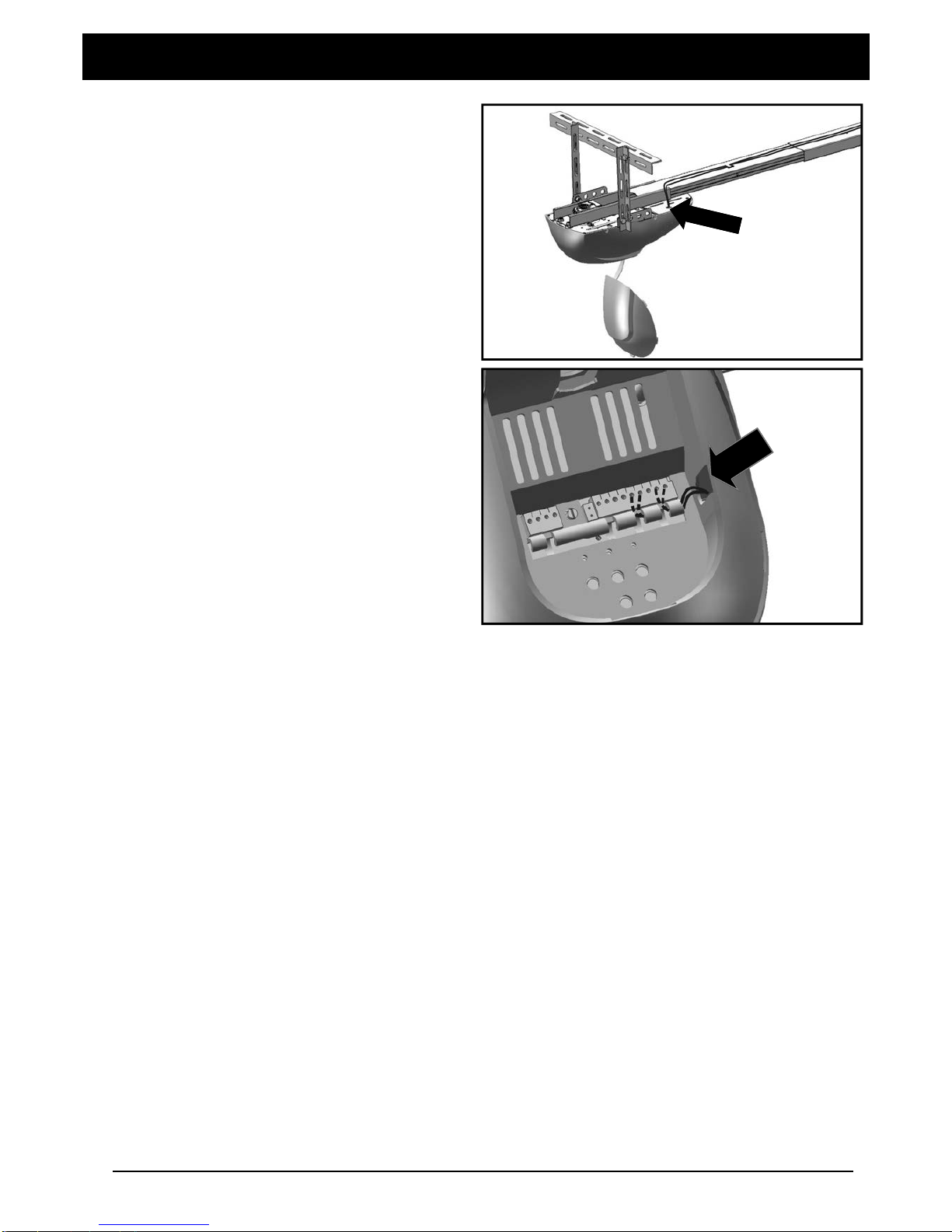
STEP 16. (OPTIONAL)
Locate photo eye wires on top of rail assembly and slide it
into guiding clips.
Trolley
Hitch Pin
Clevis Pin Short
8
Double Overhand Knot
Release Instruction Card
Release Knob
15
(1)
(2)
18
Assembly 05
17
STEP 17.(OPTIONAL)
Put signal wires through the hole on the up right side.
STEP 18.(OPTIONAL)
Pull out the signal wires from hole of the front side
9
Autres manuels pour BOL5
1
Ce manuel convient aux modèles suivants
1
Table des matières
Autres manuels BOSSCO ouvre-porte de garage

Manuels ouvre-porte de garage populaires d'autres marques


Craftsman
Craftsman 139.53924 Manuel utilisateur

Chamberlain
Chamberlain MyQ 940ESTD Manuel utilisateur

Automatic Technology
Automatic Technology GDO-9V1 SecuraLift Manuel utilisateur

Westfalia
Westfalia 19 36 07 Manuel utilisateur

Chamberlain
Chamberlain HD520EVP Manuel utilisateur

Cardin
Cardin BL Series Manuel utilisateur