BOSSCO RVH1004Z Manuel utilisateur

1
l
RVH1004Z/1008Z/1016Z
US411Z/811Z/611Z
X11Z
H.264 DVR
User Manual
SW-11Z-I1-V1.0-E
This document contains preliminary information and subject to change without notice.

2
This symbol is intended to
alert the user to the presence
of unprotected “Dangerous
voltage" within the product's
enclosure that may be strong
enough to cause a ris of
electric shoc .
This symbol is intended to
alert the user to the presence
of important operating and
maintenance (servicing)
instructions in the literature
accompanying the appliance.
WARNING
TO REDUCE THE RISK OF FIRE OR
ELECTRIC SHOCK, DO NOT EXPOSE
THIS APPLIANCE TO RAIN OR
MOISTURE.
NOTE:
This equipment has been tested
and found to comply with the limits for a
class digital device, pursuant to part 15 of
the FCC Rules. These limits are designed
to provide reasonable protection against
harmful interference when the equipment is
operated in a commercial environment.
This equipment generates, uses, and can
radiate radio frequency energy and, if not
installed and used in accordance with the
instruction manual, may cause harmful
interference to radio communications.
Operation of this equipment in a residential
area is li ely to cause harmful interference
in which case the user will be required to
correct the interference at his own expense.
Disposal o Ol
d Electrical & Electronic Equipment
(Applicable in the European
Union and other European countries with separate collection systems)
This symbol on the product or on its pac aging indicates that this product shall not be treated
as household waste. Instead it shall be handed over to the applicable collection point for the
recycling of electrical and electronic equipment. By ensuring this product is disposed of
correctly, you will help prevent potential negative consequences for the environment and
human health, which could otherwise be caused by inappropriate waste handling of this
product. The recycling of materials will help to conserve natural resources. For more detailed
information about recycling of this product, please contact your local city office, your household
waste disposal service or the shop where you purchased the product.
Notice: Ghosting or fractured images may occur on the screen when there is a suddenly surge
or lightning stro e which cause damage on IC in the DVRs.

3
Table of Contents
CHAPTER 1 MAIN MENU SETUP ____________________________________ 4
1-1 RECORD SETUP ____________________________________________ 5
1-1.1 Quality & Frame Rate Setup _____________________________ 6
1-2 EVE T SETUP ______________________________________________ 6
1-2.1 MOTIO SETUP ________________________________________ 7
1-2.1.1 MOTIO AREA SETUP ______________________________ 7
1-2.2 SE SOR SETUP ________________________________________ 8
1-3 SCHEDULE SETUP __________________________________________ 9
1-3.1 Schedule Record Setup _________________________________ 9
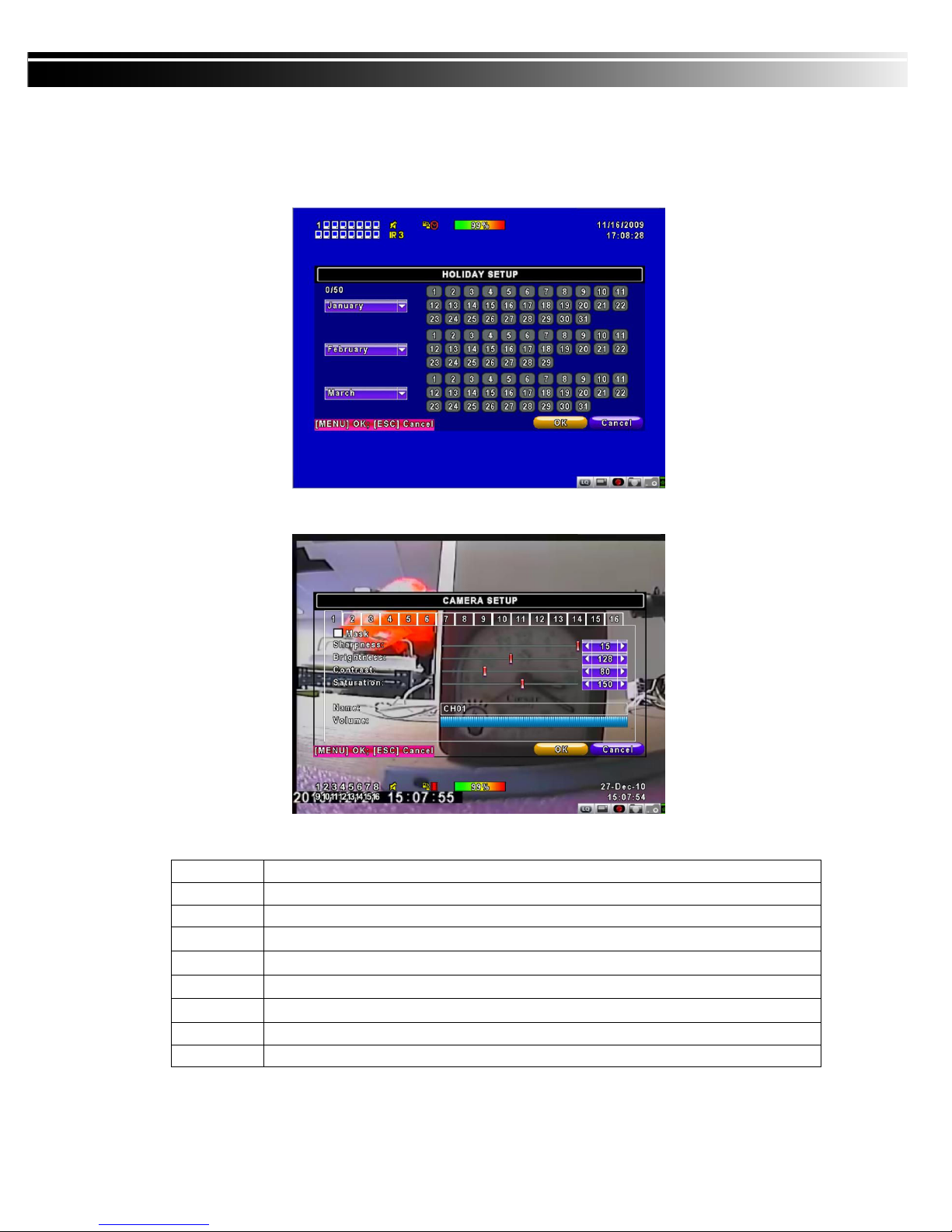
1-3.2 Holiday Setup _________________________________________ 10
1-4 CAMERA SETUP ___________________________________________ 10
1-5 ACCOU T SETUP __________________________________________ 11
1-5.1 Permission Setup ______________________________________ 11
1-5.2 User Picture Setup ____________________________________ 12
1-6 ETWORKI G SETUP _______________________________________ 12
1-6.1 ETWORKI G SETUP __________________________________ 13
1-6.1.1 DHCP ___________________________________________ 13
1-6.1.2 LA _____________________________________________ 13
1-6.1.3 ADSL ____________________________________________ 14
1-6.1.4 3G ______________________________________________ 14
1-6.2 HTTP Setup ___________________________________________ 15
1-6.3 DD S Setup __________________________________________ 16
1-6.4 Mail Setup ____________________________________________ 17
1-7 PTZ & RS485 SETUP _______________________________________ 18
1-8 SYSTEM SETUP ____________________________________________ 19
1-8.1 DISPLAY SETUP _______________________________________ 19
1-8.2 DATE/TIME SETUP _____________________________________ 20
1-8.2.1 CHA GE DATE & TIME ____________________________ 21
1-8.2.2 TIME ZO E A D DAYLIGHT SAVI G TIME SETUP ____ 21
1-8.2.3 I TER ET TIME SETUP ___________________________ 22
1-8.3 BUZZER & RELAY SETUP ______________________________ 22
1-8.4 SPOT SETUP__________________________________________ 23
1-9 UTILITY SETUP ____________________________________________ 24
1-10 DIAG OSTIC ______________________________________________ 25
CHAPTER 2 BACKUP & SEARCH ___________________________________ 26
2-1 BACKUP SETUP ____________________________________________ 26
2-2 SEARCH SETUP ____________________________________________ 29
2-2.1 EVE T SEARCH _______________________________________ 29
2-2.1.1 CRITERIA SETUP FOR EVE T SEARCH _____________ 30
2-2.2 TIME SEARCH_________________________________________ 31
CHAPTER 3 Remote Software Installation and Setup ___________________ 32
3-1 AP Software Installation and instruction ______________________ 32
3-2 How to do remote monitoring through IE _____________________ 34
3-3 How to do remote monitoring through JPEG VIEWER(Only Monitor
Function) _____________________________________________________ 35
3-4 AP Software Operation ______________________________________ 37
CHAPTER 4 Specification __________________________________________ 39

4
CHAPTER 1 MAIN MENU SETUP
To enter the main menu and set up DVR, log-in account and user password are required.
The default password of the administrator is “123456”. Please chec the “Account Setup” for
related setup of other log-in users.
Table 1-0.1 Some definition of virtual eyboard.
Item Description
Switch between capital and small letters.
/ Switch between numbers and letters.
Press to cancel the setup, and re-choose the login
account.
Delete the last character.
Enter to identify the password. It will enter the set
up menu, If the password is verified.
Space ey

5
Table 1-0.2 The operation of remote control under the setting menu
Item Description
Switch to different options under one item
Switch to different items
MENU Save setup and bac to LIVE mode
ESC Bac to Upper level of menu without saving
ENTER Enter the menu, or display virtual eyboard
PS. The initialization of new-installed HD is required before recording, please refer to “ UTILITY
SETUP” for detail.
1-1 RECORD SETUP
Item Description
HDD FULL
Select STOP to stop recording or OVERWRITE to reuse the
HDD when HDD is full
「Stop」:Stop Recording
「Overwrite」:Start to overwrite that begin from the oldest data
of HDD, and continue to record.
OSD position X Setup OSD X axis
OSD position Y Set up OSD y axis
OSD position setup Set up OSD axis
Video Preservation Setup the video preservation period. Recorded video will be
deleted automatically after expiry of preservation period.
Quality & Frame Rate
Setup
Setup the quality and frame rate for each channel under normal
recording and event recording type.
Note:
::
:4CH DVR will display 4 channels and 8CH DVR will display 8 channels.

6
1-1.1 Quality & Frame Rate Setup
Item Description
Normal setup/
event setup Select recording mode
Resolution Select recording resolution: NTSC:352x240, 704x240, 704x480
PAL:352X288,704X288,704X576
Record Type You can setup quality and FPS separately for record type.
No. Chec /unchec the box enable/disable selected channel recording
Quality Select quality: Below Basic/ Basic/ Normal/ High/ Highest
FPS Select recording frame rate.
(The number of sheets in accordance with the actual models)
Auto Assign each channel with its maximum accessible fps
Note:
::
:4CH DVR will display 4 channels and 8CH DVR will display 8 channels.
1-2 EVE T SETUP
Item Description
Motion Setup Enter to set up motion detection
Sensor Setup Enter to set up sensor detection

7
1-2.1 MOTIO SETUP
Item Description
Alarm Duration(Seconds) When motion detect,the number of seconds continuous alarm
1~16 You can setup independently for each channel.
Enable Chec the box to Enable/Disable motion detection for each channel.
Sensitivity
Drag the white bar or press ◀ ▶ to set up Sensitivity from
value 0 to 10 for each channel. The higher value you set the
higher sensitivity it will be.
Motion Area Setup Enter to setup motion detection area
Note:
::
:4CH DVR will display 4 channels and 8CH DVR will display 8 channels.
1-2.1.1 MOTIO AREA SETUP
The motion detection has been divided into 22x18 grids. The default detection area is
full screen as it mar ed in transparent for local DVR and purple for remote access.
Areas deselected for motion detection are mar ed in red for both local and remote site.

8
Item Description
Mask Mouse Selection Switch between “select” and “deselect” for cursor-dragging function
All Area Detection Select entire screen as detection area.
Mask All Area Deselect entire detection area.
Continue Continue setup
Exit & Save Save setup and leave
Exit & Discard Cancel setup and leave
1-2.2 SE SOR SETUP
Item Description
Sensor Popup Chec the box to Enable/Disable popup screen function for all
channels. When Sensor is detected in LIVE mode, the detected
channel image will pop up in full screen display.
All O Set all sensor off
All Low Set all sensor polarity low
All High Set all sensor polarity high
Sensor Polarity Clic or press ▼ to select between HIGH, LOW voltage for triggering
sensor detection or OFF to turn off polarity for each channel
Low Polarity:Sensor has not been triggered. When connected,
sensor will be turned on..
High Polarity:Sensor has been triggered. When connected, sensor
status will be turned off..
O :Sensor is deactivated, and will not be turned on/off.
Note:
::
:4CH DVR will display 4 channels and 8CH DVR will display 8 channels.

9
1-3 SCHEDULE SETUP
Except from starting recording manually, you can also setup the recording time by wee s
and schedule including normal, motion detect, and recording type.
Item Description
Page Each page provides 10 schedules for setup. 5 pages in total.
Holiday Setup Enter to setup holiday, up to 50 days, other than wee ends,.
View Event/ Motion/
Sensor Setup
View Normal/ Motion/Sensor
Note:
::
:4CH DVR will display 4 channels and 8CH DVR will display 8 channels.
1-3.1 Schedule Record Setup
Clic on the time on the left side. The setup menu will be displayed. You can have
detail setup by dates, Time and event.

10
1-3.2 Holiday Setup
Since holidays are different by different country and region, you can setup the holiday of
your location accordingly.
1-4 CAMERA SETUP
Item Description
1~16 You can setup independently for each channel.
Mask Chec the box to Enable/Disable mas function for LIVE mode
Sharpness Drag the bar or press ◀ ▶ to adjust Sharpness of your camera from value 0 to 15.
Brightness
Drag the bar or press ◀ ▶ to adjust Brightness of your camera from value 1 to 255.
Contrast Drag the bar or press ◀ ▶ to adjust Contrast of your camera from value 1 to 255.
Saturation Drag the bar or press ◀ ▶ to adjust Saturation of your camera from value 1 to 255.
Name Set up name of each channel
Volume Audio volume under LIVE mode and recording mode can be adjusted.
Note:
::
:4CH DVR will display 4 channels and 8CH DVR will display 8 channels.
Ce manuel convient aux modèles suivants
6
Table des matières


