BME Aircraft 37% Scale Ultimate Biplane Manuel utilisateur

BME Aircraft
37% Scale Ultimate Biplane
BME 37% Ultimate Ver 1.0 3/15/2004 Page 1

BME 37% Ultimate Ver 1.0 3/15/2004 Page 2

BME 37% Ultimate Ver 1.0 3/15/2004 Page 3
INTRODUCTION
Congratulations! You have just purchased an outstanding aerobatic aircraft in the form of the BME Aircraft
37% Ultimate Biplane. The Ultimate has long enjoyed a reputation of being one of the best flying RC aerobatic
designs in existence. This reputation was earned and well-proven over the years in what was perhaps the most
prestigious RC event in the world – the Tournament of Champions (TOC). The outstanding flight
characteristics of the Ultimate were recognized and demonstrated in the late 80's and early 90's when it was the
aircraft of choice for almost every TOC competitor and again in 2002 when the Ultimate was flown to 1st place
against the best pilots and RC aircraft in the world.
Until now the Ultimate has been readily available only in smaller sizes of 1.20 and below and most recently in
very large versions of 40% scale and above. To fill the large void of 100cc sized aircraft BME has introduced
the 37% Ultimate – just the right size to present well with the 40% monoplanes but a lot easier to handle than
the giants and a the perfect match for the new BME 110 Extreme engine!
SPECIFICATIONS
Wing Span 80.5"
Wing Area 2254 sq. in.
Weight 26-27 lbs. With
BME Extreme110
Wing Loading 26-28-oz./sq. ft.
Recommended Engine 100cc or Greater (lighter is better)
Construction Light Ply, Balsa, Foam & Fiberglass
Plug-in Wings Aluminum Spar Tubes
Plug-in Horizontal Stabs Aluminum Spar Tubes
Covering Monokote
Bottom Wing Incidence Zero (0) Degrees
Top Wing Incidence 1.5 Degrees Negative (preset by cabanes)
Engine Right Thrust Approximately 3 Degrees.
Engine Down Thrust 0 Degrees to +1 Degree
Elevator High Rates 20 degrees Up and Down
Elevator Low rates To Suit
Bottom Wing Aileron High Rates 25 Degrees Up and Down
Top Wing Aileron High Rates 20 Degrees Up and Down
Aileron Low Rates To Suit
Rudder Rates To Suit (rudder is very effective)
3D Rates Max All Surfaces and Adjust Down to Suit
Read through the instruction booklet and study the parts and photos to become familiar with the construction
before actually beginning work. The kit is highly prefabricated and the instructions detailed to guide you
through all major elements of the assembly processes.
Good Luck and Happy Flying!
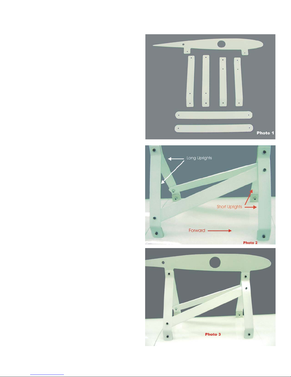
ASSEMBLE CENTER CABANES
1. Refer to photos 1-3 and locate the 7 metal
cabane pieces consisting of 2 long
uprights, 2 short uprights, 2 diagonals and
1 center root rib.
2. Note that the two shorter uprights are
installed towards the front of the fuselage
while the longer uprights are installed
towards the rear. This provides the correct
amount of negative incidence for the top
wing. Also note that each upright has an
additional hole drilled towards one end.
The forward uprights have the hole
towards the top while the rear uprights
have the holes towards the bottom. See
photo 2.
3. Loosely bolt the uprights to the OUTSIDE
of the tabs that protrude through the top of
the fuselage using the supplied cap head
screws, nuts and lock washers. Be sure to
install the short uprights towards the front
of the fuse with the additional holes
towards the top and install long uprights
towards the rear with the extra holes
towards the bottom.
4. Loosely bolt the two diagonals between
the front and rear uprights as shown in the
photos. They are installed to the inside of
the uprights.
5. Install the metal root rib between the front
and rear uprights as shown in photo 3. It
is captured between the front and rear
uprights.
6. Tighten all nuts and bolts while keeping
the uprights vertical.
BME 37% Ultimate Ver 1.0
3/15/2004 Page 4

MOUNT THE WHEELS AND WHEEL PANTS ( This part will be revised with new style )
BME 37% Ultimate Ver 1.0
3/15/2004 Page 5
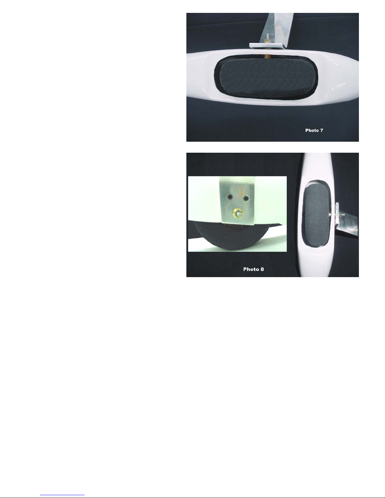
1. Refer to photos 4-8 and locate the landing
gear, wheels, wheel pants, axles, wheel
collars and wheel pant mounting screws as
shown in photo 4.
2. Enlarge the existing hole on the inner side
of each wheel pant so that the axle nut will
just pass through the hole. Use
progressively larger drill bits to enlarge
the hole to help prevent chipping and to
keep the hole centered. See photo 5.
3. On the outer side of each wheel pant is a
molded depression. Drill a hole in each
wheel pant at this location that is large
enough for the head of the axle to pass
through. This hole will help with the
assembly process and final adjustment.
4. Referring to photo 6, assemble the
axle/wheel assemblies as follows: Take
an axle, slip a washer onto the axle
followed by a wheel, another washer and a
wheel collar. Do not tighten the wheel
collar yet and do not put the nuts on the
axles.
5. Slide the assembly into a wheel pant by
holding the wheel over the opening of the
wheel pant, pushing the head of the axle
screw into the wheel pant cut out and out
the hole on the outside of the wheel pant.
Pull the head of the screw outward until
the other end of the axle with the wheel
collar will drop into the opening where it
can be pushed through the hole in the
inner wheel pant side.
6. Thread an axle nut onto the axle such that
the flange part of the nut is facing toward
the end of the threads as shown in photo 6.
Thread the nut on so that approximately
5/8" of the threads are showing.
7. Note, The landing gear on the Ultimate
are swept rearwards. In other words,
they slant towards the rear of the
airplane when viewing from the side.
Keeping this in mind identify the right
and left gear legs and wheel pant
assemblies. Take one assembly and
push the axle threads through the axle
hole in the aluminum landing gear and
install the other flanged nut to secure it
to the landing gear.
8. Mount the wheel pants to the landing
gear legs using the screws provided.
There are 2 screws for each wheel pant
and the holes have already been drilled
in the pants and the blind nuts have
already been installed at the factory
9. The axle will need to be adjusted
inward/outward in order to position the
wheel in the cut out. The adjustment is
performed by screwing the axle in and
out of the landing gear leg using a
Phillips screwdriver through the hole in
the outer wheel pant side. Once it is in
the correct position the wheel collar may
be tightened to secure the wheel in the
proper location. The wheel is captured
by the screw head of the axle on one
side and the wheel collar on the other
side.
10. Check all clearances to ensure that the wheels will not rub against the cut outs. If more clearance is
required enlarge the cut outs using a Dremel tool (use a mask!). When everything fits correctly and
there is adequate clearance between the wheel and wheel pant, tighten the axle nuts securely. It is a
good idea to use a thread-locking compound such as red Loctite to prevent the axle nuts from
coming loose.
BME 37% Ultimate Ver 1.0 3/15/2004 Page 6
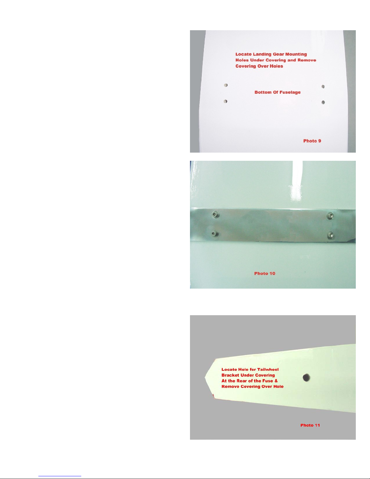
MOUNT THE LANDING GEAR TO THE FUSELAGE
1. Refer to photo 9 and locate the holes for the
landing gear mounting screws underneath
the covering. Pressing firmly with a finger
will allow feeling the holes under the
covering.
2. Using a sharp Exacto blade cut the covering
from each hole.
3. Install the landing gear using 4 socket head
bolts, lock washers and flat washers as
shown in photo 10. The blind nuts have
already been installed at the factory. Thread
locking compound may be used to ensure
that the mounting bolts do not come loose
from vibration.
MOUNT THE TAIL WHEEL BRACKET TO THE FUSELAGE
1. Refer to photo 11 and locate the hole for the
tail wheel bracket underneath the covering
at the rear of the fuse. Pressing firmly with
a finger will allow feeling the hole under the
covering.
2. Using a sharp Exacto blade cut the covering
from the hole.
BME 37% Ultimate Ver 1.0
3/15/2004 Page 7

3. Test fit the tail wheel bracket into the hole.
It may be necessary to remove the paint
from the bracket and/or to radius the rear of
the hole to accept the bracket.
4. Once the bracket fits all the way down into
the hole secure it with the 2 formed straps
and sheet metal screws as shown on photo
12.
5. Install the tail wheel on the tail wheel mount
using the supplied wheel collar as shown in
photo 13.
UNCOVER SERVO CUT OUTS AND SERVO
LEAD EXITS IN WING PANELS AND MOUNT
AILERON SERVOS.
1. Refer to photo 14 and locate the holes for
the Aileron Servos underneath the covering
on the bottom of the bottom wing. Trim the
covering and use a trim iron to tuck the
covering down into the servo holes As
shown in photo 14
BME 37% Ultimate Ver 1.0 3/15/2004 Page 8

2. Locate the servo lead exit holes on the
top of the bottom wing between the two
strut mounting tabs. Cut the covering
over the holes and use a trim iron to tuck
the covering down into the holes as
shown in photo 15. These holes are
where the servo extensions for the servos
in the top wing panels will be connected
as they pass up through the wing struts on
their way to the servos in the top wing
panels.
3. Thread 2 servo extensions through each
bottom wing panel from the wing root.
One extension exits the hole in the top of
the wing panel, which will later be
connected through the strut to the servo in
the top wing panel. The 2nd extension is
plugged into the servo in the bottom wing
panel. Mount the aileron servos in the
bottom wing panels after running both
extensions through each panel. See
photos 16 & 17. Note: All aileron servo
arms must point towards the wing tips in
order to line up with the hard points
embedded in the ailerons.
BME 37% Ultimate Ver 1.0
3/15/2004 Page 9
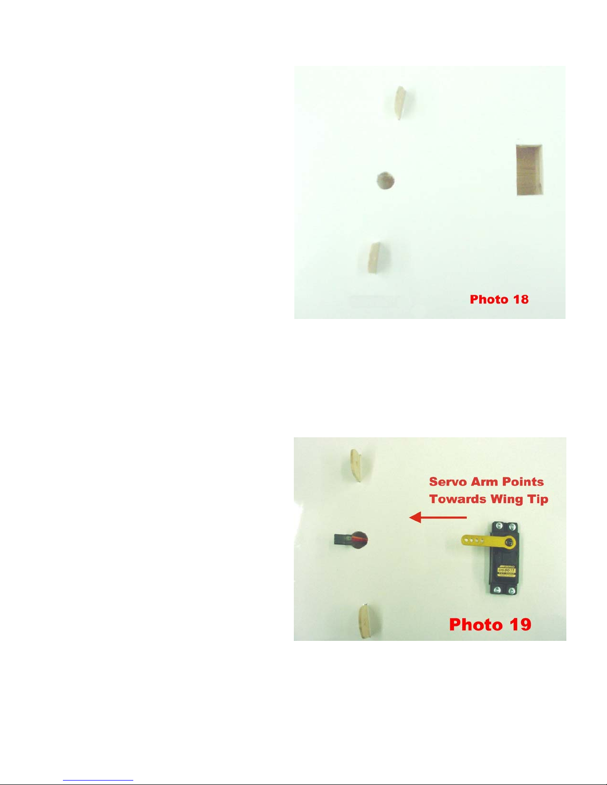
4. Locate the servo cut out and servo lead
exit holes on the bottom of the top wing.
Cut the covering over the holes and use
a trim iron to tuck the covering down
into the holes as shown in photo 18.
5. Mount the aileron servos in the bottom
of the top wing and route the servo leads
out through the exit holes as shown in
photo 19. Note: all aileron servo arms
must point towards the wing tips to
ensure lining up with the embedded hard
points in the ailerons.
BME 37% Ultimate Ver 1.0 3/15/2004 Page 10
Table des matières
Autres manuels BME Aircraft Jouet


