16 DS901001-005 DS901001-005 17
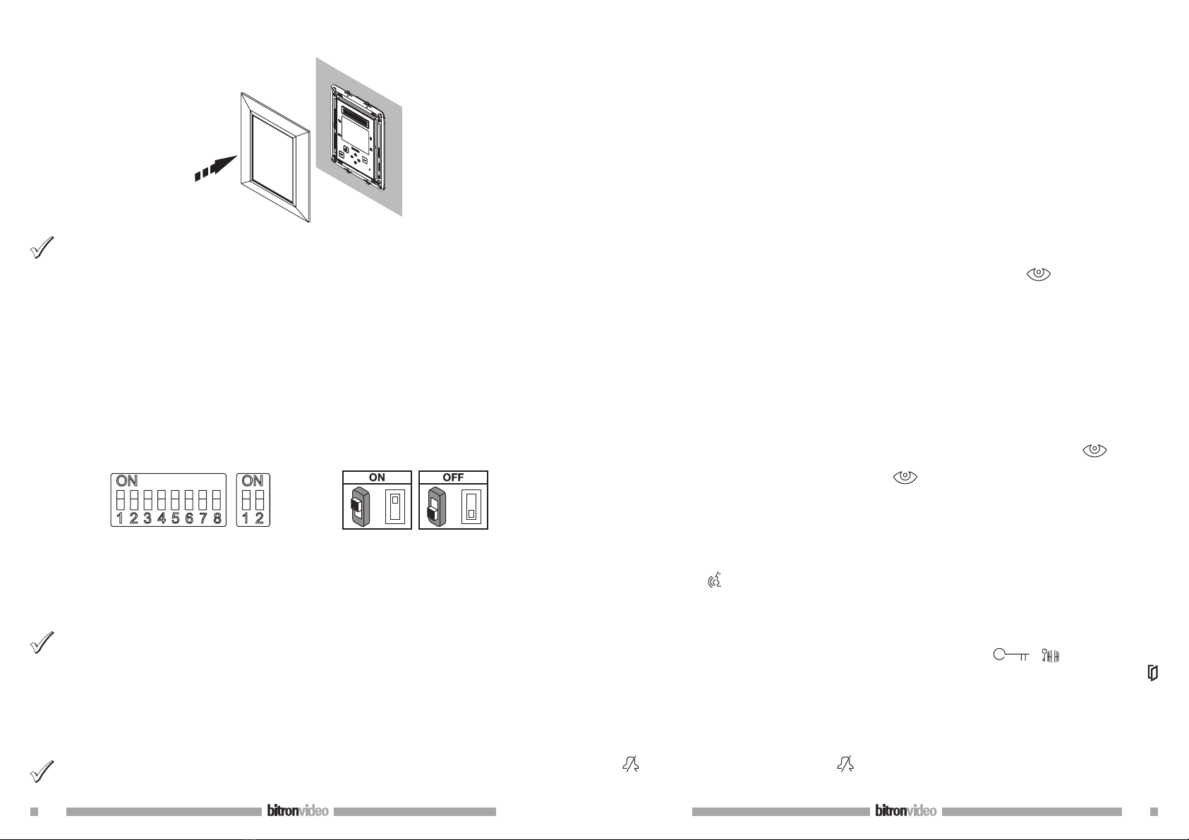
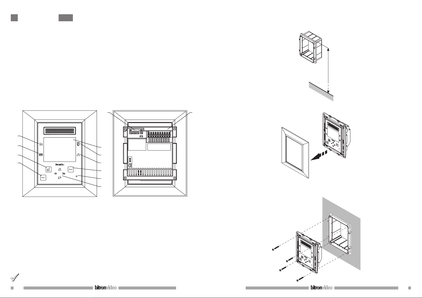
Mount the clip-on front panel on the support.
Mount the front panel on the support by pressing deeply into all its surface. All front panel locks must
be fixed. It is suggested to mount and remove the front panel with the video door phone NOT powered.
Otherwise, temporary malfunction of touch buttons could occur.
Remove the protection film.
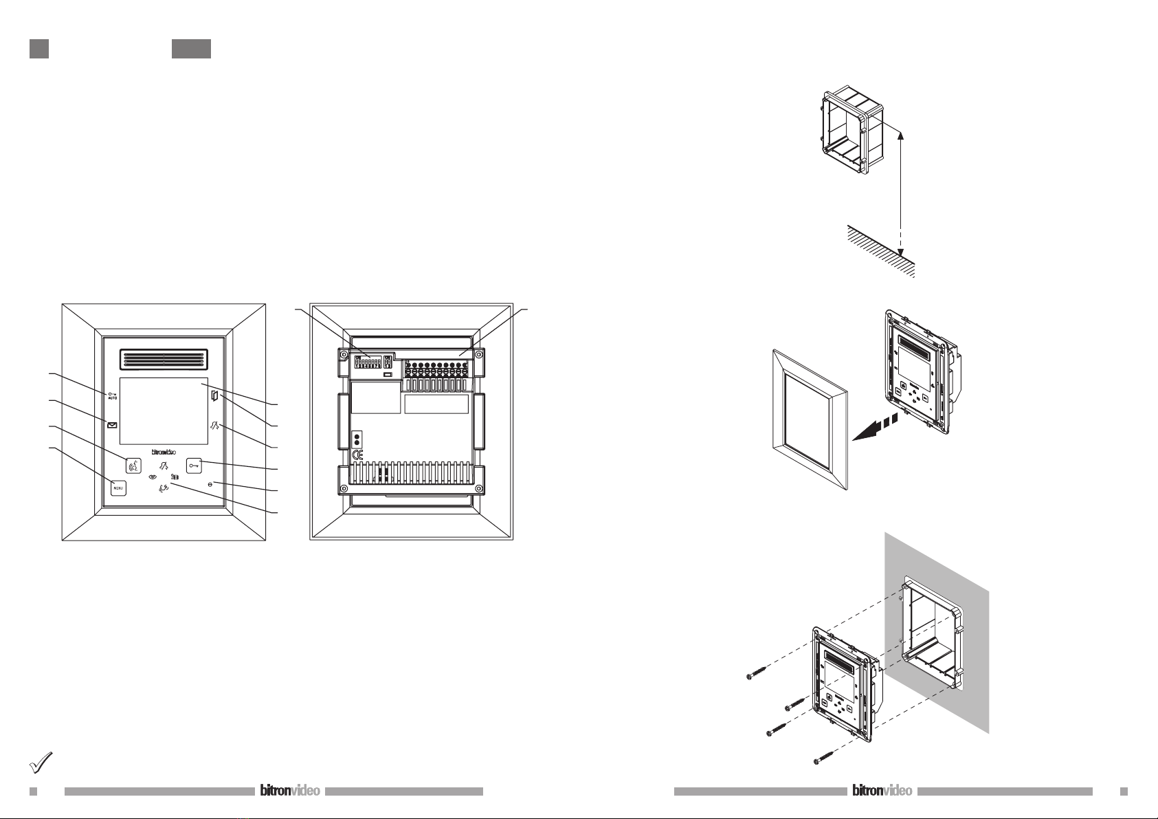
1.1 TERMINAL PINS DESCRIPTION
BUS IN Connection to the system BUS
BUS OUT Connection to the next device for an in/out connection
S+ Call repeat
S- Call repeat
PFloor call
AVE BUS + Connection to BUS AVE +
AVE BUS - Connection to BUS AVE -
1.2 CONFIGURATION OF APARTMENT STATIONS BRACKETS
= =
ON
ON
Default values: all video door phones default configuration is the following:
USER = 127
INTERNAL CODE = 0
Therefore, for the proper operation of the system, always pay attention to dip switches, in order to configure
them with the correct value.
For dip switch settings, see the system manual provided with the power supply Ref. 1083/20.
CODE: user code.
Set a number from 0 to 127, according to the following rules:
In the column there must not be any apartments with the same user code.
If there are apartment stations in parallel in the same apartment, these must have the same user code.
The user codes of the same column must be consecutive.
To set the desired code, use the dip switches from 2 to 8 (2= most significant bit - 8= less significant bit);
the dip-switch 1 must be set to OFF.
INT: apartment internal code.
Set a number from 0 to 3, according to the following rules:
If in the apartment there is only one station, the internal code must be set to 0.
In apartments, up to 4 apartment stations in parallel with the same user code and different internal codes
can be connected.
•
•
•
•
•
The internal code identifies each station of the same user. This means that intercom calls can be addressed to
the single internal code in the same apartment.
In case of intercom calls to different apartments, in case of calls coming from door units and in case of floor
call, all the user apartment stations always ring. Consider also the following information:
after receiving a call, the internal code 0 rings immediately; the internal codes 1, 2 and 3 ring in
sequence.
If the call comes from a video call station, the internal code 0 turns the monitor on.
However, the other apartment stations of the same user can press the button to turn their video door
phone, turning off the other (‘video transfer’ function).
2 FEATURES
2.1 RECEIVING A CALL
When a video door phone call is received from a door unit, the video door phone emits the call ring, with the
ring tone selected by the user and the display automatically turns on, showing the image coming from the
door unit.
If in the apartment there are several apartment stations in parallel, the stations ring in sequence. The user
internal code 0 also performs the video door phone power-on, if the call comes from a video door phone call
station. In this case, during the off-hook waiting time (60s from the call), the other internal codes can turn
their video door phone on by pressing the auto-on button (‘video transfer’ function), until one of the
video door phones of the called user answers.
If the image is already displayed, press the button to cyclically display images coming from other control
cameras of the caller station only.
After picking the handset up, the image coming from the main camera will only be displayed in the apartment
stations which has answered.
Therefore the camera image will be displayed on one apartment station at a time.
2.2 ANSWERING THE CALL
By pressing the button , the user establishes a communication with the caller (the button pressed starts
blinking). By pressing again the button, the communication is closed and the display turns off.
2.3 DOOR LOCK RELEASE DURING A CALL AND OPEN DOOR INDICATION
After a call is received from a door unit or during the communication with a door unit, the pedestrian or
driveway gate can be opened by pressing the buttons and respectively.
If the call modules are provided with open door sensor (and the absence service is not active), the led can
indicate if the door is really open or not: the led lights up steady if the open door is the main one, and blinks
if the open door is the secondary one.
2.4 RINGER LOUDSPEAKER MUTE
This function allows to disabled the call ringer. To activate this function, press the button . When the
function is activated, the led MUTE turns on and when a call is received, the device will not ring.
2.5 ADDITIONAL RINGER
The video door phone is provided with two terminal pins (S+, S-) for the connection of an additional ringer
or a relay. This ringer is activated with any call ring.
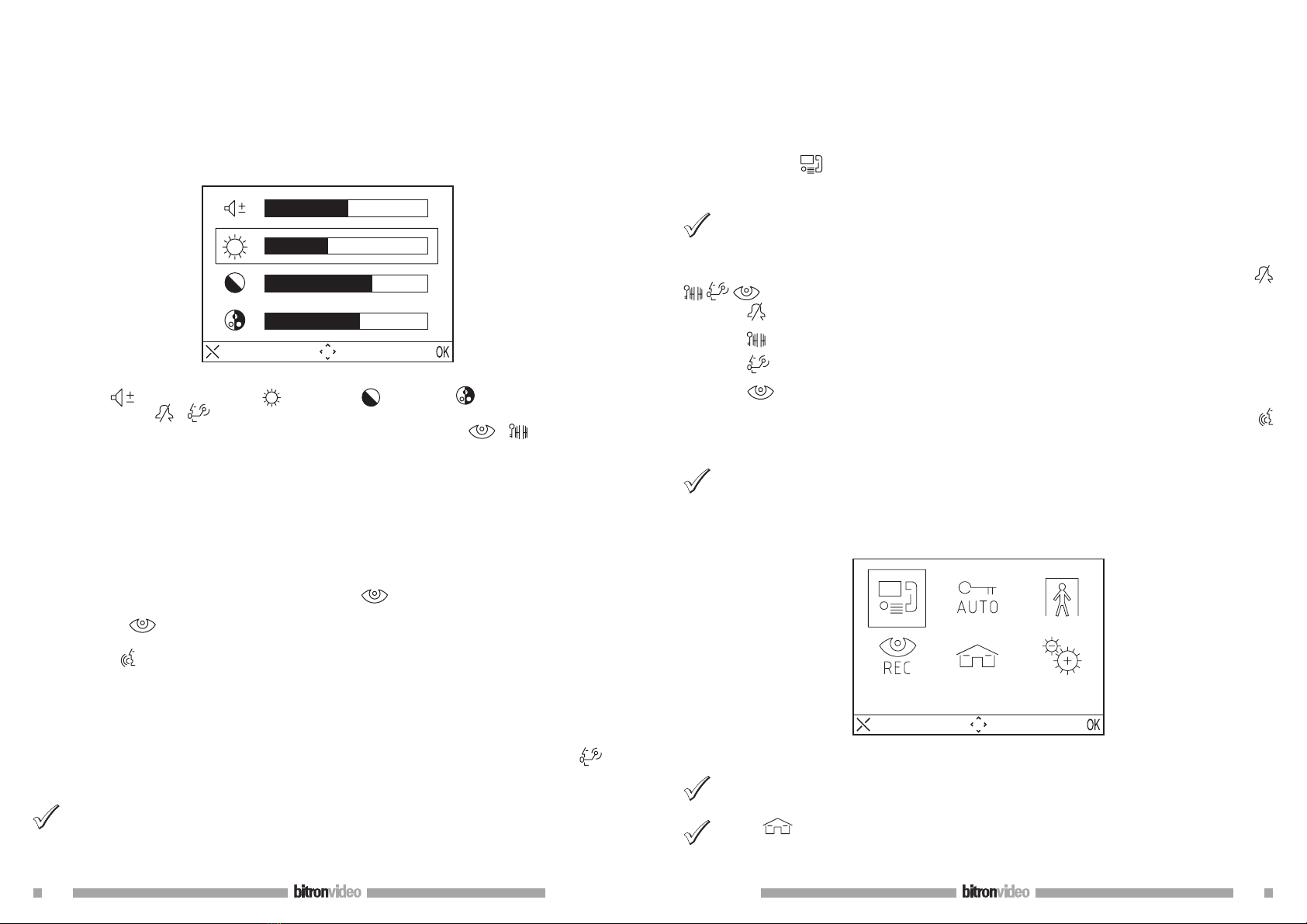
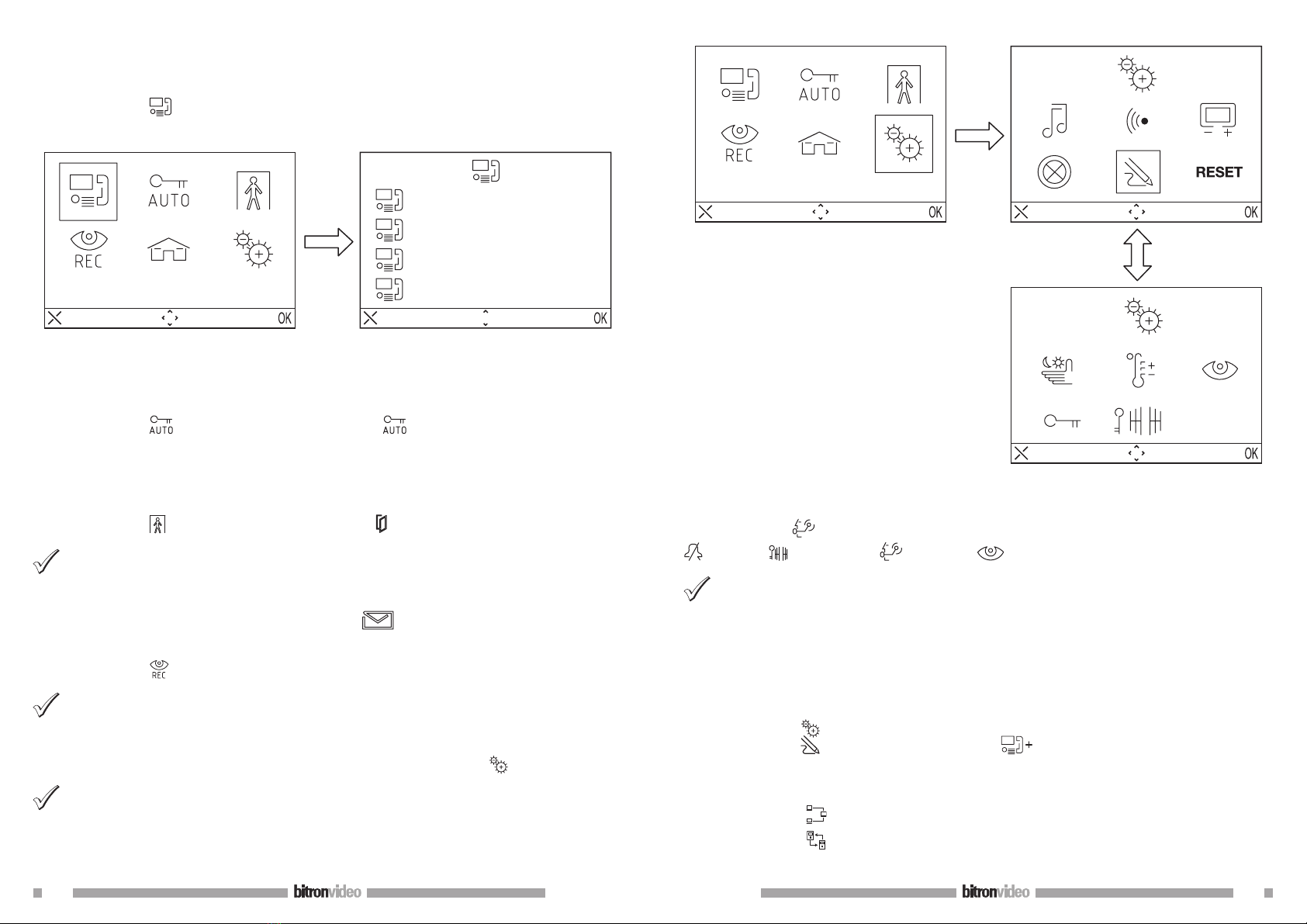
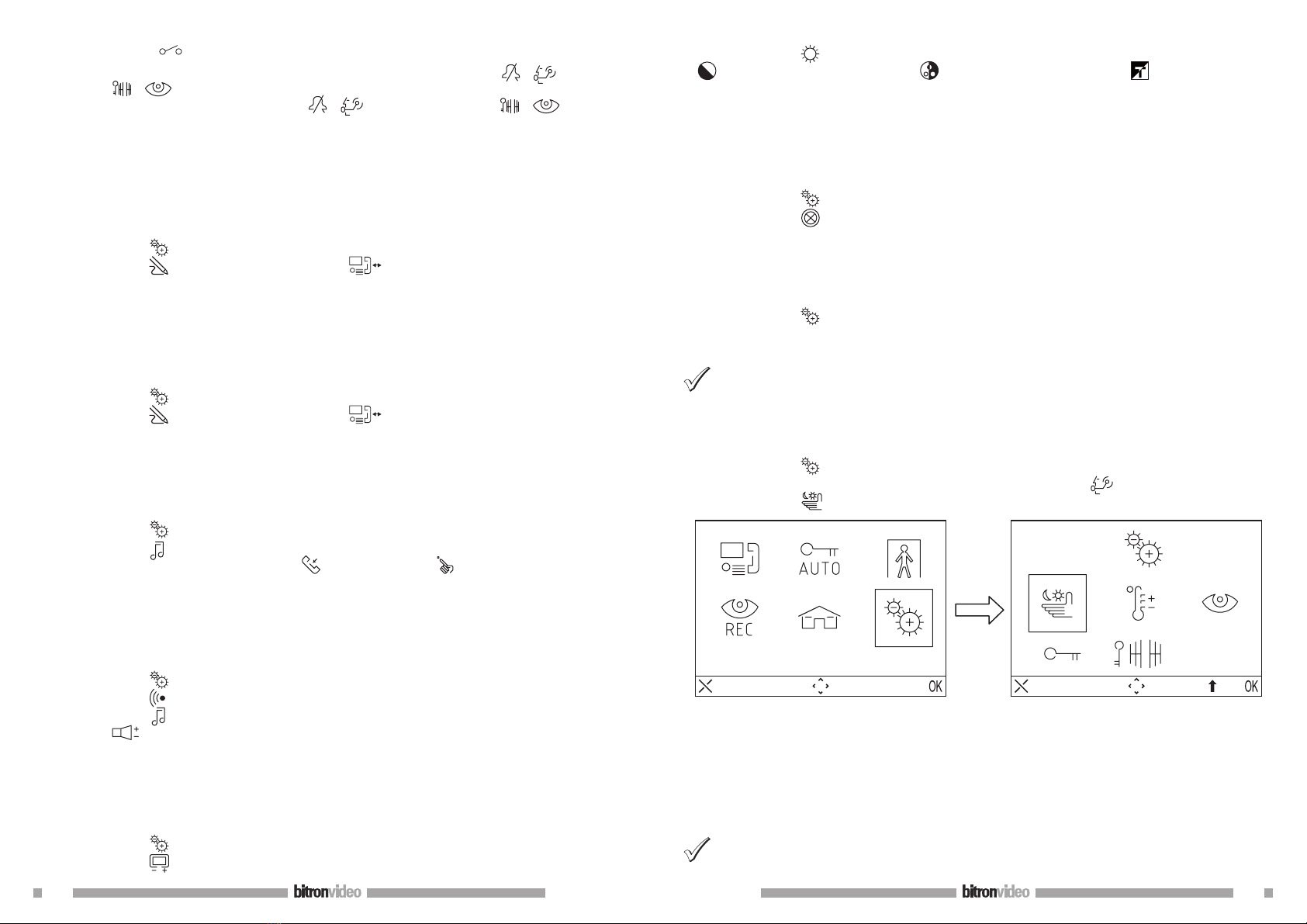
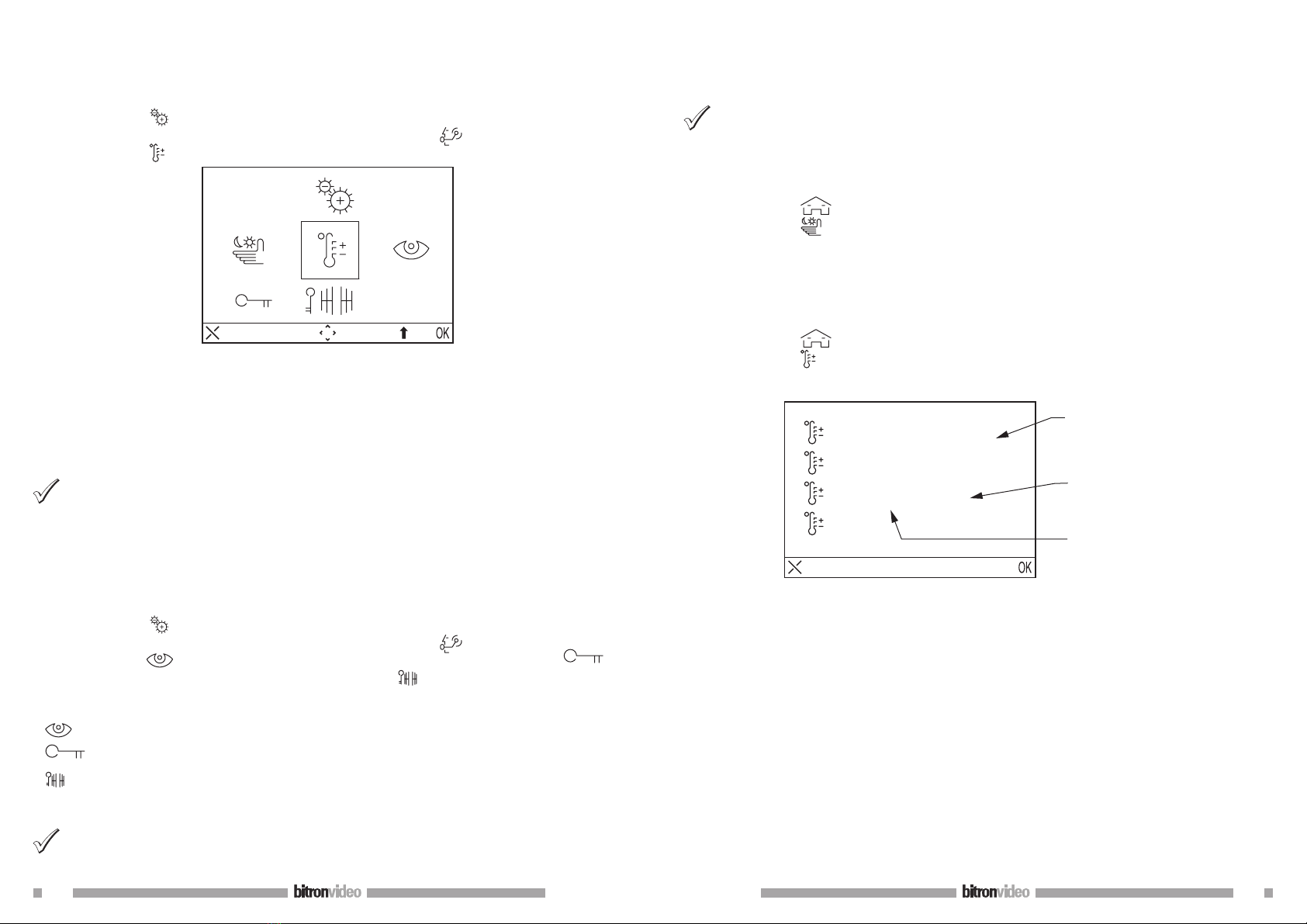
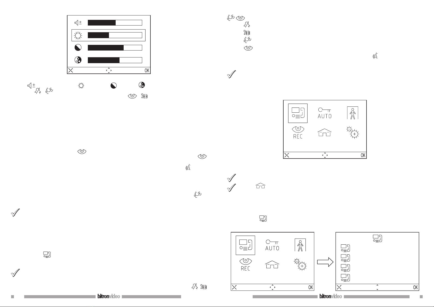
2.6 AUDIO / VIDEO SETTINGS DURING CALL
When a call is received or during communication, some audio/video adjustments can be performed: by pressing
the button MENU, the following screen appears
•
•