05-01-2004 CPO 315 & 350 Page 8 / 34
3. Description of machine
The 315 & 350 program consists of 4 models which have the same basic construction and
each of which meets the same high quality requirements.
The constructive differences apply to the application and the specific wishes of the user.
All versions are standardly equipped with a machine base with incorporated cutting oil tank
and pump.
All versions are fitted with a tolerance-free long-life worm and worm wheel. The worm gear
runs in an oil bath case and is virtually maintenance-free.
All versions are fitted with a double, self-centring material vice.
The machine can mitre, slot and cut recessed corners in both directions. For this last form of
operation it is of special importance that the saw unit as a whole can turn around its axis.
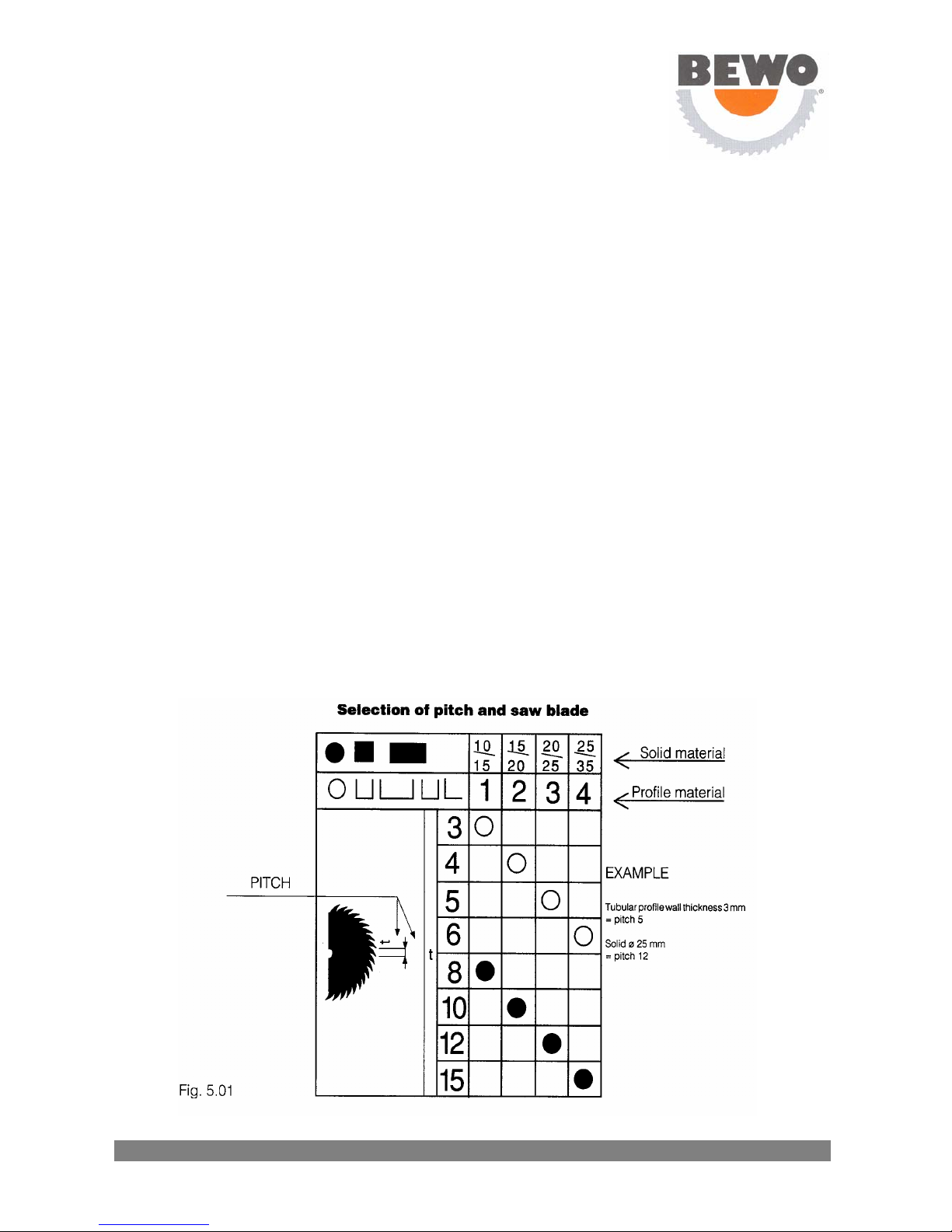
The machine can saw various profiles in various dimensions and cross-sections. A survey of
these can be found in chapter 5.3 “Sawing capacity”.
The patented protective guard opens and closes automatically. The saw blade can easily be
exchanged. The machine as standard is equipped with an adapter for the saw blade (see
technical data). If ordered a different adapter can be supplied.
4 Installation
4.1 Installation and mounting
Unpack the machine.
•Determine where the sawing machine will be placed. In doing so take into account the feed
and discharge of materials, optional built-on accessories, maintenance and repairs.
•Remove the plastic plug from the saw head (fig. 4.01 B). If so required a lifting hook M20 DIN
580 can be screwed into the hole.
•Place the saw unit - if necessary by means of hoisting equipment – on the machine base
(cover at the rear) and attach each other.
•Secure the machine to the floor. The necessary holes have already been made in the
machine base.
•Install the handle in the saw head and lock it (fig 4.01A).
•Install the 3 short handles in the boss of the machine vice.
•Install the stretcher in the clamp.
•Slide the plastic tube coming from the cooling pump onto the tap which is positioned on top
of the protective guard of the saw unit (fig 4.02A).
•Check on the level gauge of the saw head whether it contains sufficient oil. If necessary
fill up (fig. 4.01, see arrow).
•Install the cover at the rear of the machine base.
•Install the saw blade (see chapter 5.4).