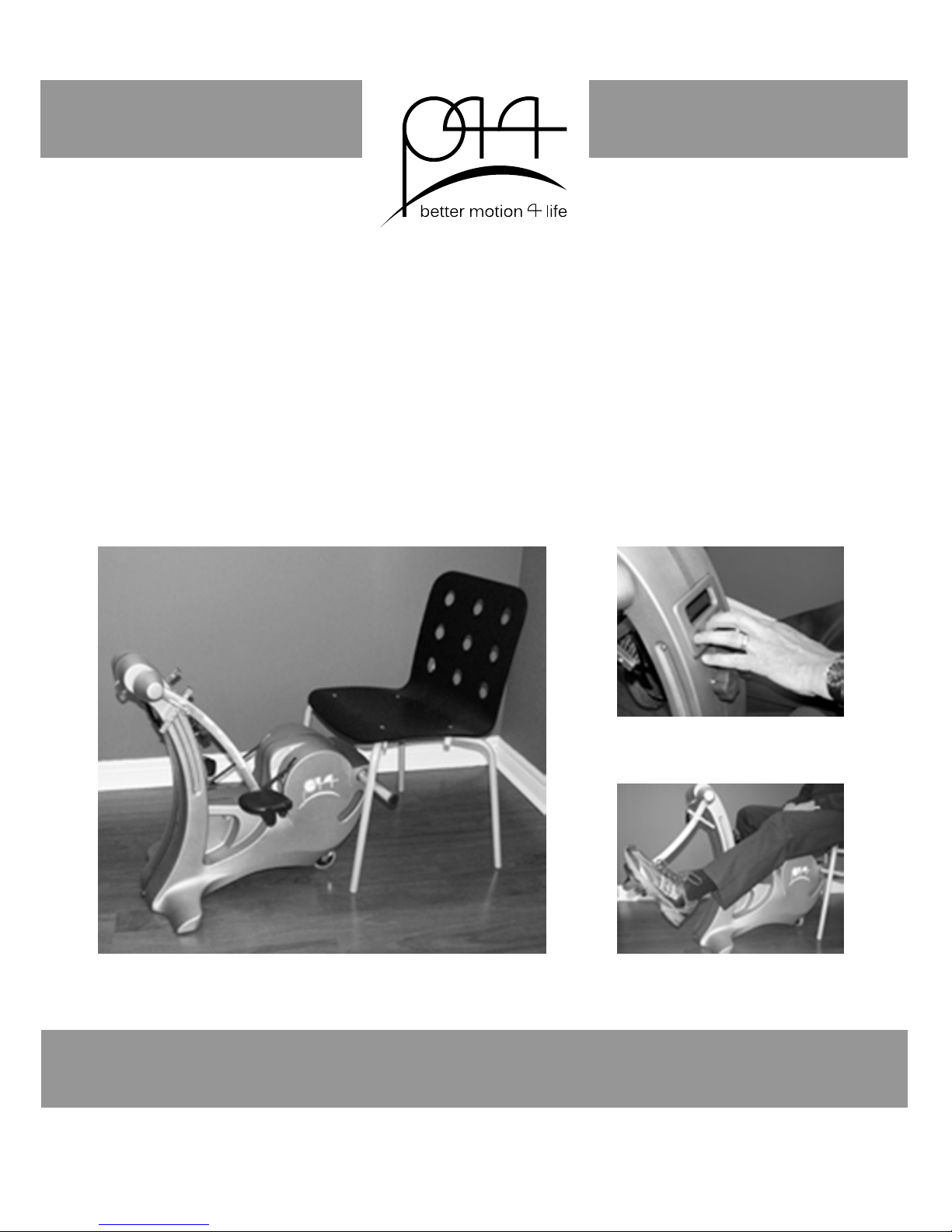
BETTER MOTION GROUP Chair-Mounted Stepper Manuel utilisateur

P44 Stepper
User Manual

Table of Contents
Introduction 1
Safety Warning 2
Overview of Parts 2
Attaching to Chair 3
Manoeuvring Around 4
Setting Pedal Stops 4
Getting On 5
Setting the Resistance (models without LCD) 6
LCD Operation 7
Removing Battery (models with LCD) 13
Charging Battery (models with LCD) 14
Technical Data 15
Preventative Maintenance 15
Scheduled Maintenance- Replace Brake Pads 16
Troubleshooting 19
Location of Serial Number 21
Customer Service 21
Warranty 22
Owner Identication and Information 22
Safety Warning
Always see your physician before beginning any exercise program, especially if you have
pre-existing health conditions. If you feel faint or dizzy while using this product, stop imme-
diately and seek medical help or advice. Do not operate this product if it appears damaged.
Read this manual in its entirety before use and refer back to it as necessary.
The caution symbol will appear in the outer margins of a page to
indicate a potentially hazardous situation that may result in injury.
!
CAUTION
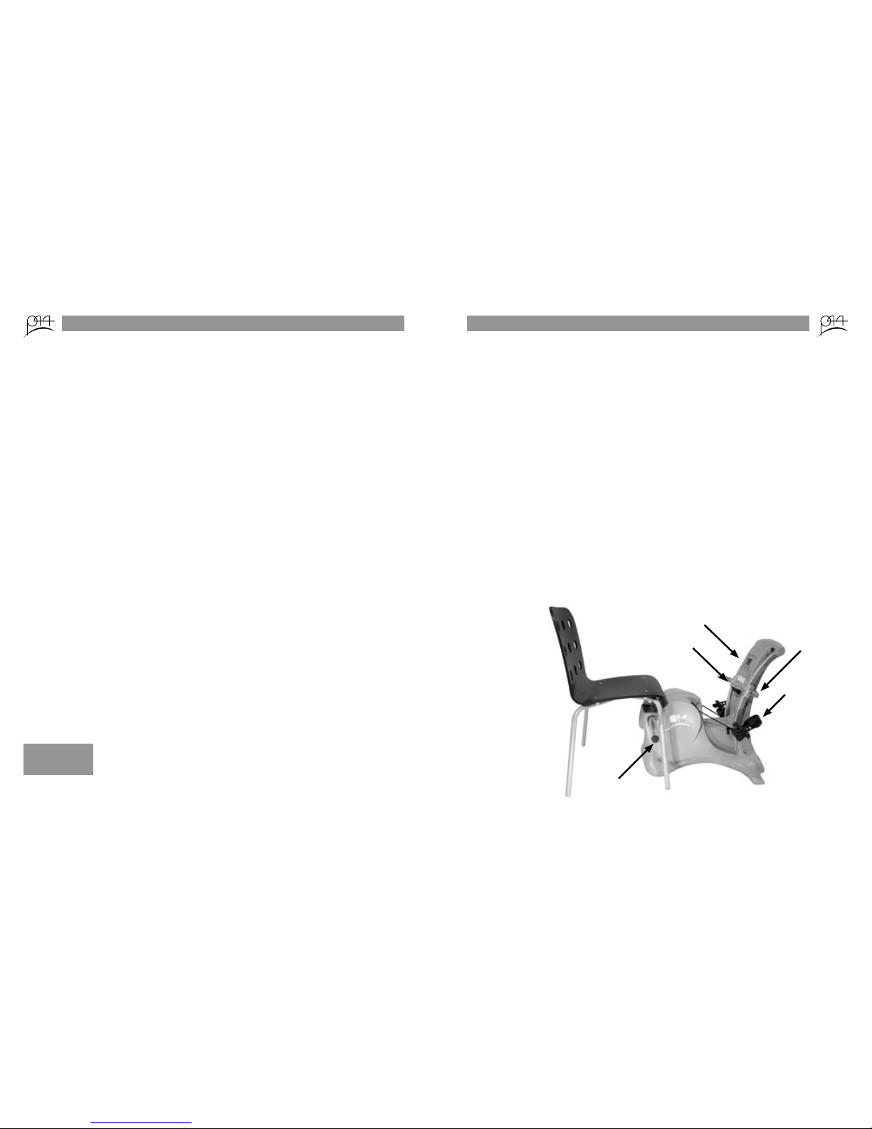
12
chair pole
pedal
pedal stop
resistance knob
LCD
Introduction
Thank you for purchasing the P44 chair-mounted stepper. This device incorporates a unique
leg motion that allows for independent resistance setting, stroke length, and stroke rate from
leg-to-leg. P44 accommodates a decreased knee range of motion better than circular pedal
travel and also acts as a strengthening device, making it ideal to help in the treatment of:
• osteoarthritis
• total knee replacement
• ACL damage
• stroke recovery
• generalgeriatrictness
Time, work, power, and the resistance setting are not only displayed on the LCD, but this
data is stored and can be wirelessly transferred via bluetooth® to a PC for analysis. P44
more accurately charts patient progress electronically.
All of this technology is wrapped in a stylish package that is light weight, highly portable,
and attaches to any 4-legged chair (including wheelchairs) in seconds.
Overview of Parts

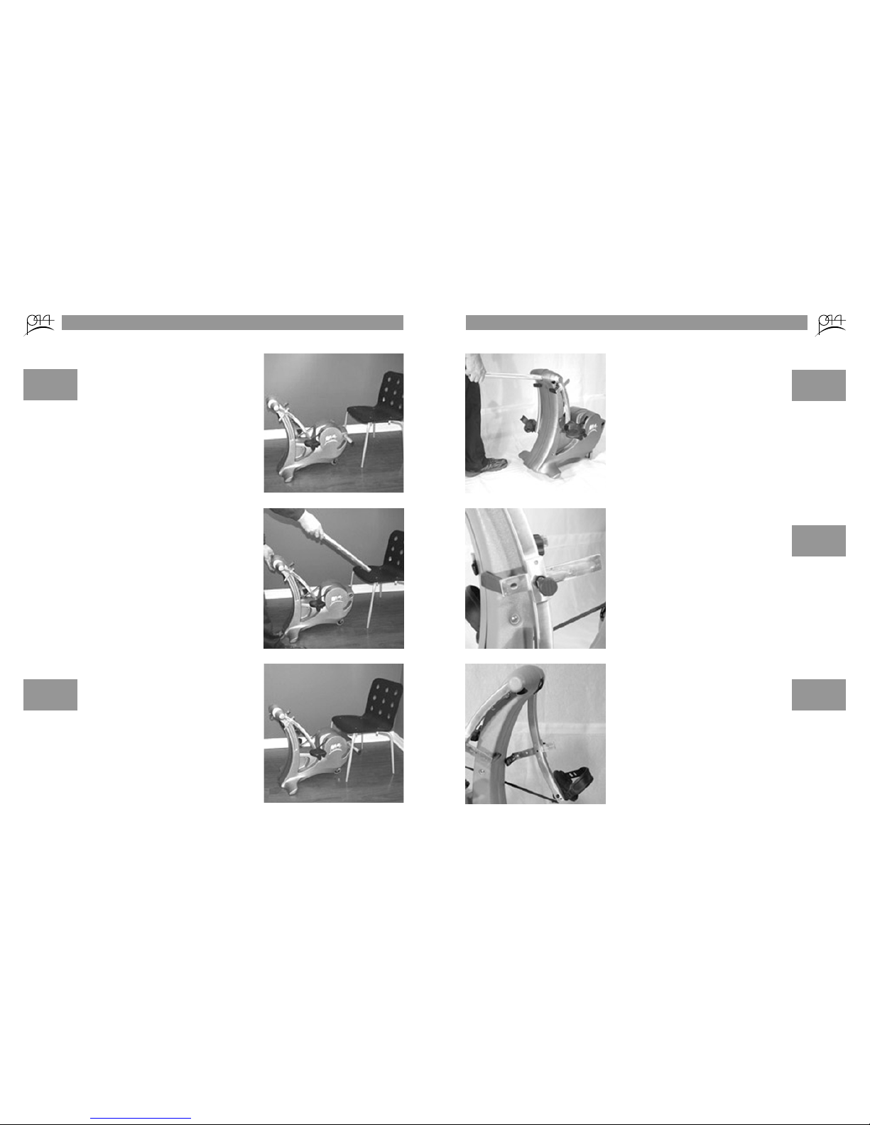
Set a chair with a suitable seat
height (at least 17.5 inches from
ground) and chair leg width (so
that pole extends at least 2 inches
past outside legs) in front of P44.
Pull the pole free of P44, grasp
the front handle and gently roll
the device underneath chair seat
far enough that the pole can be
slid behind the front legs.
Slide the pole into the slot in P44,
making sure it catches behind
both front legs and extends at
least 2 inches past each leg.
Attaching to Chair
Improper
chair leg
width could
result in P44
becoming free
of chair legs.
Ensure P44 is
securely
attached via
chair pole
to front legs
before use.
3
!
CAUTION
!
CAUTION
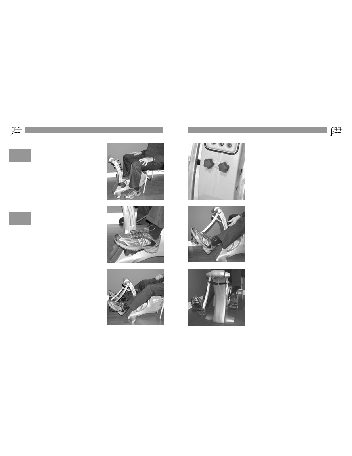
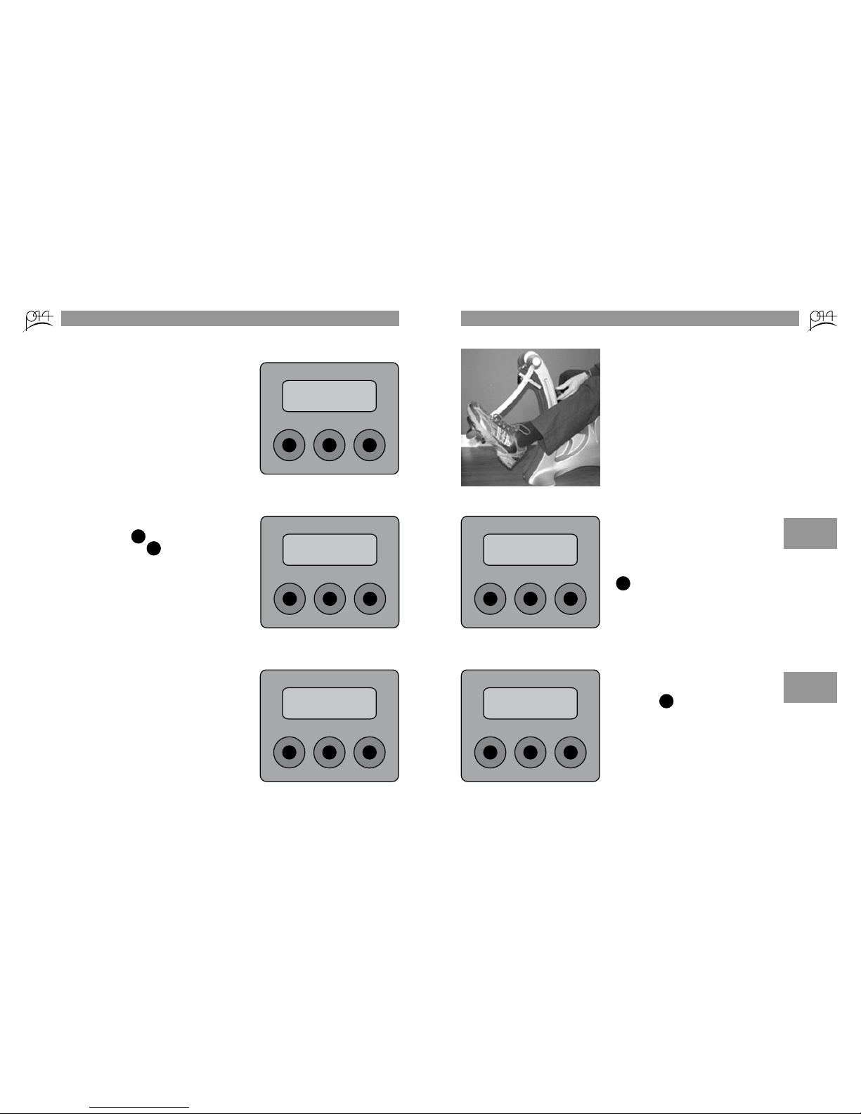
With one hand pull the pedal arm
toward the front of P44 and hold
it while pulling the pin that se-
cures the pedal stop to the pedal
arm with the other hand.
Slide the pedal stop bar towards
the front of P44 for a starting posi-
tionrequiringlesskneeexion
and in the opposite direction for
a starting position that requires
morekneeexion.Thepedal
stop can also be removed from
the slot and inserted the reverse
way for a starting position requir-
ingalmostnoexionatall.
Setting Pedal Stops
Releasing the
pedal arm
while adjusting
the pedal stop
could result in
arm springing
back.
Never induce
a knee exion
that is painful
or uncomfort-
able.
4
!
CAUTION
!
CAUTION
Manoeuvring Around
The chair attachment pole is also
used as a handle to manoeuvre
P44 around. Insert it into the hole
in the front and lift up. The higher
you lift, the easier it is to push
P44 in a straight line. Avoid pull-
ing P44- the pole can slip out and
it is harder to manoeuvre.
!
CAUTION
Ensure the
pole is in far
enough by
pushing it
into the hole
until you meet
resistance.

Approach P44 attached to a chair
from either side and lift one leg
up and over to the other side.
Sit down with one leg on either
side of P44.
Alternatively, the user can also
beginseatedrstandtheP44
then manoeuvred into place by
someone else.
Place the ball of each foot on the
pedal on both sides.
Getting On
5
Steady your-
self on back of
chair.
Extend both legs out together or
alternatively to begin use.
If foot is in
danger of slip-
ping off pedal,
use adjust-
able strap to
secure.
!
CAUTION
!
CAUTION
6
Setting Resistance (models without LCD)
The resistance is controlled by the
two knobs below the information
sticker. The left knob controls re-
sistance for the left pedal and the
right knob controls resistance for
the right pedal. (From here, you
can also follow the instructions on
the information sticker).
Extend the left pedal out once to
test the current resistance. Turn
the left knob clockwise to in-
crease the resistance and counter-
clockwise to decrease the resis-
tance.
Extend the left pedal out again
and adjust as required.
Repeat on the right side.

7
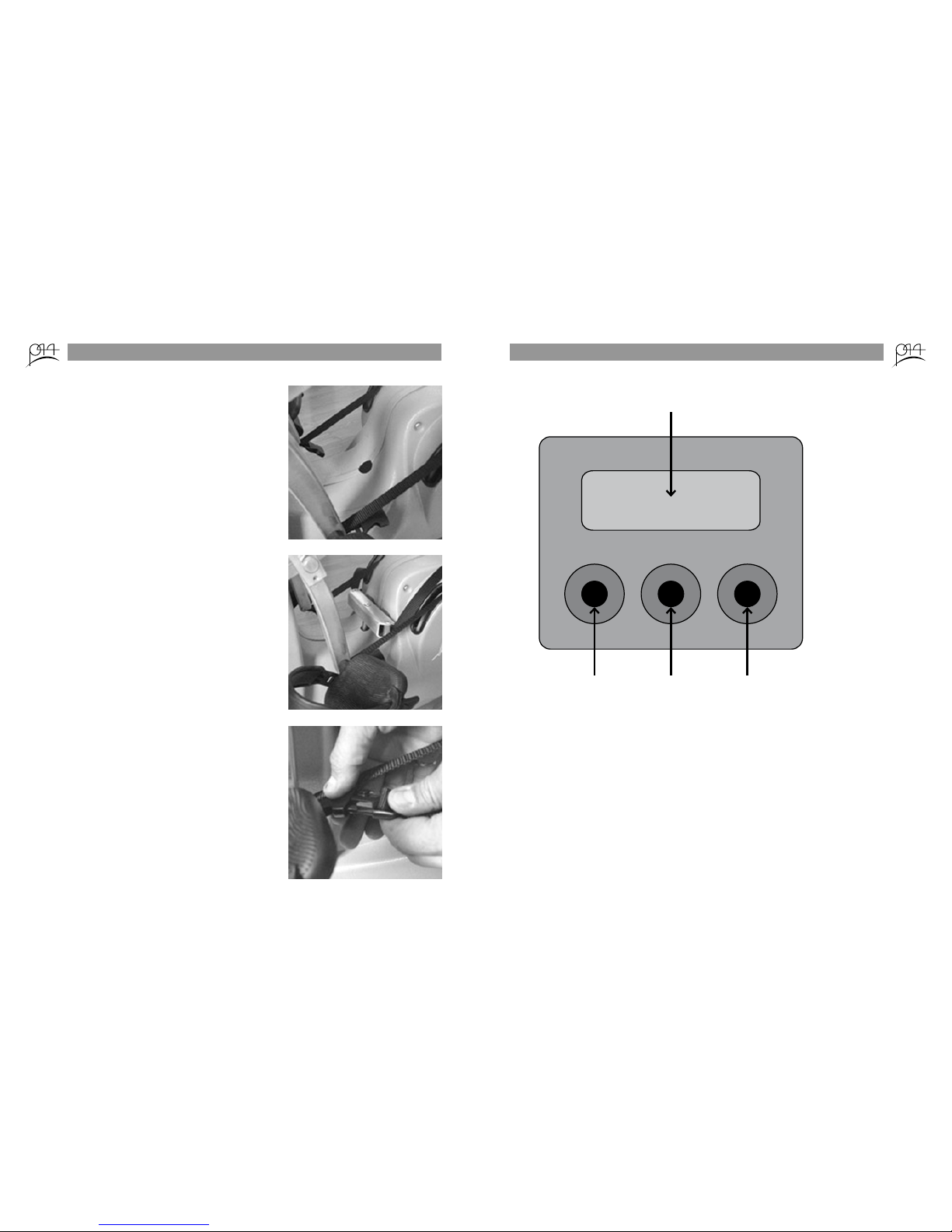
Remove the black plastic plug
from the hole located on the
bridge.
Slide the aluminum bracket rod
side down, with the foam pads
touching the P44, into the hole as
far as it will go.
Clip each side-release clip into
the mating end located on each
pedal. Adjust the length of the
strap according to the height of
theuserand/orthedegreeofex-
ion desired.
Connecting Leg Linkage Attachment LCD Operation
8
L CR
screen
left key centre key right key
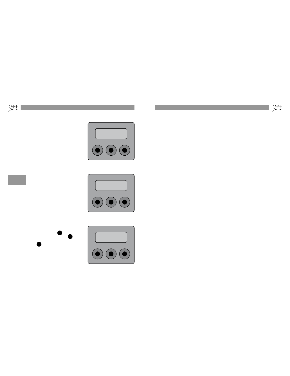
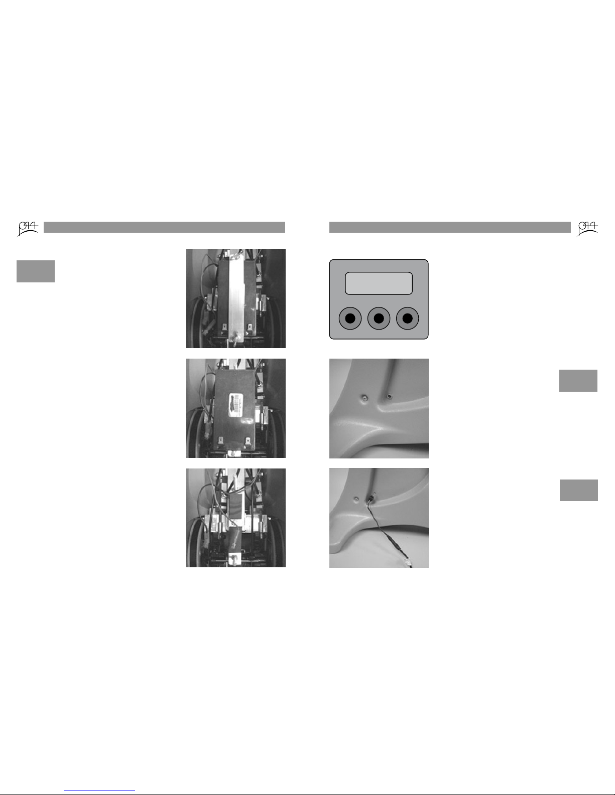
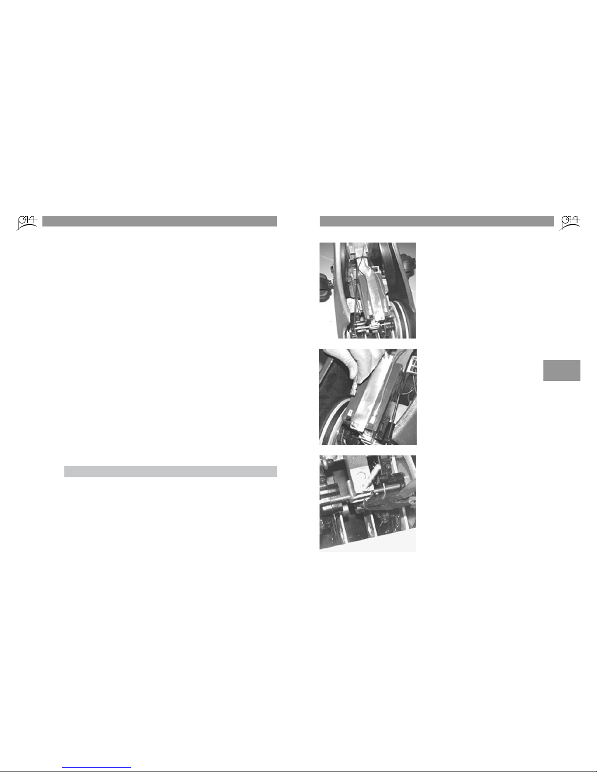
The LCD is required to set the level of resistance as well as display the
time, work, and power of the workout session. The optional wireless
bluetooth® transfer of stored data is also initiated via the LCD.

LCD Operation: Setting the Resistance
9
L CR
WELCOME TO P44
BETTER MOTION 4 LIFE
Press any of the three keys to turn
the LCD on and the following
message will appear. Press any
key again to set the resistance.
L CR
FORCE LBS C = OK
PUSH R FOR KGS
To set the resistance level in lbs
press ; to change the units to
kgs press
C
R
L CR
L FORCE 0.0 LBS
for less force turn
The left side resistance must be
setrst.Theindicatorwillini-
tially show 0.0 lbs. The scroll-
ing prompt will inform you
that turning the left hand knob
counter-clockwise decreases the
resistance and turning the same
knob clockwise increases the
resistance.
LCD Operation: Setting the Resistance
10
Turn the left hand knob clockwise
half a turn to increase the resis-
tance and then extend your left
leg out twice to see the current
resistance reading on the LCD.
L CR
L FORCE 13.5 LBS
for less force turn
Ifyouarenotsatisedwiththe
level of resistance, repeat the
steps above to increase or de-
crease the resistance. Once you
aresatised,nishbypressing
L
L CR
R FORCE 0.0 LBS
for less force turn
Repeat the same steps to set the
resistance on the right side and
then press to begin the work-
out.
R
!
CAUTION
Setting the re-
sistance above
50 lbs will
result in an
error and the
LCD stopping
the workout.
!
CAUTION
Do not set
a resistance
level that is
too difcult or
painful.

LCD Operation: Workout Information
11
Once the workout begins, the
LCD continuously scrolls between
time, power, and work. Press any
of the three buttons to advance
through the screens manually.
To stop the workout at any time,
press all three buttons at the same
time. The following message will
then be displayed.
Once the workout has been
stopped, press to review the
current workout, press to
continue the workout and press
to reset the system.
L CR
L WORK 23.5 CAL
R WORK 20.5 CAL
L CR
workout complete
!
CAUTION
Be sure to
press all three
buttons simul-
taneously or
the workout
will not be
stopped.
L
C
R
L CR
workout complete
press l to review the
LCD Operation: Data Transfer
12
Coming Soon...

Place P44 carefully on its back-
side. Remove the red and black
leads from the terminals.
Unscrew the two wing nuts and
remove the aluminum battery
plate from the bolts.
Removing Battery (models with LCD)
Crossing the
leads or plac-
ing on incor-
rect terminal
could result in
an electrical
shock.
13
!
CAUTION
Pull the battery up and away from
the body.
14
When the battery is low, a warn-
ingwillashontheLCD.
The input for the battery charger
is located on the right side of the
body, down by the foot.
Plug the correct end of battery
charger cord into the input in the
body and then plug the charger
into a 120V wall socket. Charge
for a minimum of 4 hours.
Charging Battery (models with LCD)
L CR
Battery Low
!
CAUTION
Avoid an
electrical short
by always
plugging the
charger into
P44 before the
wall socket.
!
CAUTION
P44 can be
used while
plugged into
the wall.

Technical Data
15
Length
Width
Height
Unit Weight
Maximum User Weight
Resistance
Power
26 in / 66 cm
17 in / 43 cm
27 in / 68.5 cm
25 lbs / 13.5 kg
Chair-dependent
0 - 50 lbs / 22.5 kg per side
12V rechargeable DC battery
with wall pack transformer
Preventative Maintenance
Part Action Frequency
Battery Charge Every 8 hours
Plastic cover Clean w/ soapy water Weekly
Nylon straps Inspect for fraying Weekly
Cutout on bottom Vacuum lightly Monthly
16
Scheduled Maintenance: Replacing Brake Pads
Release all tension (turn resistance
knobs counter-clockwise) and
place P44 on its backside.
Disconnect the two leads from
the battery. Remove the battery
(refer to page 13).
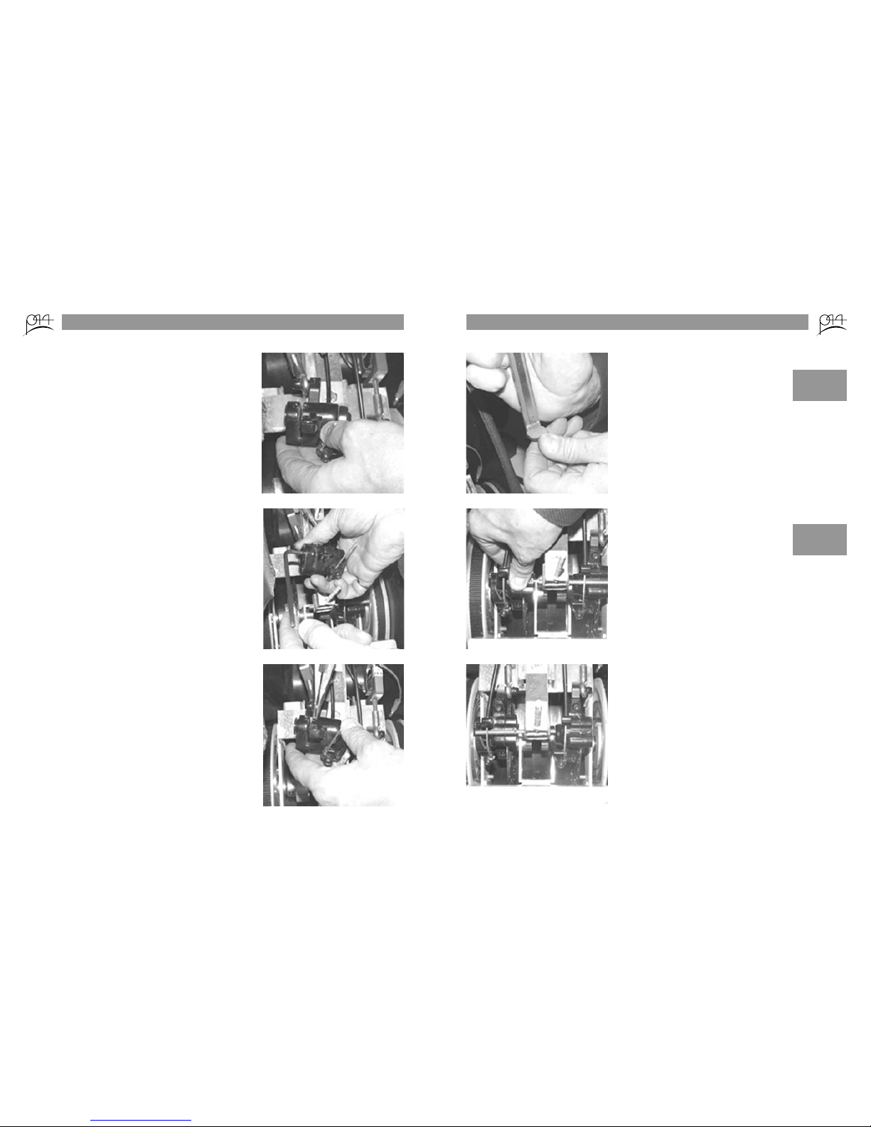
The threaded rod that secures the
two brake calipers has a pin in
the centre that needs to be pulled
with a set of needle-nosed pliers.
!
CAUTION
Touching ei-
ther the metal
of the lead or
the battery
can cause an
electric shock.

17
Slide the rod to the right and
remove the left hand caliper from
the disc by pulling up and away.
Turn it over so that the pads are
visible on the left hand side.
Take a 3/16 allen key and turn
counter-clockwise so that the tab
attached to the top of the pad
itself slides to the left and into the
slot in the caliper.
Grasp the tab attached to the top
of each pad and remove the pads
from the calipers.
18
A new pad is 2.5mm thick and a
pad less than 0.5mm should be
changed. If it is between these
thicknesses, the pad can be re-
installed and tightened, via the
allen key.
After either re-installing the exist-
ing pads or replacing with new
pads, use the allen key to tighten
the outer pad with approximately
a 2mm space between the two
pads. Turn over and slide back on
brake disc.
Once re-installed, slide the rod to
the left and repeat the same steps
to check/replace the pads on the
right side. Once both calipers
have been worked on, centre the
rod and replace the pin to secure
it in place. Re-install the battery
and place the P44 back right-side
up.
!
CAUTION
If in doubt,
replace with
a new pad. If
below 0.5mm,
little to no
reistance will
be felt.
!
CAUTION
If the space
between the
pads is less
than 2 mm,
the caliper will
not slide onto
the disc.
Ce manuel convient aux modèles suivants
1
Table des matières