BETE HydroWhirl Orbitor Tank Washing Machine
Instruction & Maintenance Manual
Page2of17
011013
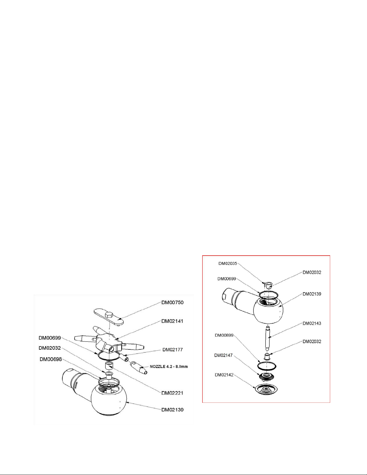
Maintenance
In order to prevent machine failures, routine maintenance should be carried out every 500 hours of
operation. This should include cleaning all internal parts and assessing the wear of seals, gears, bearing
and bushes.
Any fine solid particles left inside the machine will increase wear considerably.
Please note:
– The Orbitor requires no lubrication.
– The Orbitor approved by Bureau Veritas; a copy of certification can be provided upon request.
Attention
- Before maintenance can be carried out, it is important the machine is not contaminated with
chemicals that could be hazardous
.
- Always use the tools stated throughout this manual. These can be purchased from BETE.
- Always read the technical data thoroughly before carrying out any work on this machine.
- Never service the Orbitor head while it is hot.
- After any maintenance is carried out it is essential the machine is flushed and sterilized before
further use.
- Any parts found to be unserviceable should be replaced before further use.
- The machine should only be operated at temperatures below 95°C (200°F)
- During operation, always ensure any tank openings are completely sealed off and can withstand
the full force of the striking jet.
- If the tank being cleaned contains a combustible liquid or vapour with a risk of ignition or
explosion, the Orbitor should be properly grounded.
- The machine should be allowed to gradually reach its operating pressure. A sudden spike could
cause parts to wear prematurely or fail.
Please Note – Any cleaning fluids must be stored/disposed of in accordance with current
rules/directives.
Please Note - Always record any wear found and check the smooth operation of the
machine after maintenance.