Bentley EXP12 Fiche technique

BENTLEY EXP12
Owner’s Manual
with Assembly Instructions
Styles and colo(u)rs may vary.
Made in China.
The owner’s manual contains important safety information as well as assembly, use and
maintenance instructions.
The Ride-on Car must be assembled by an adult who has read and understands the
instructions in this manual.
Keep the package away from children and dispose of properly before use.
Keep this manual for future reference.
Officially
Licensed Product
BATTERY OPERATED RIDE-ON

On the purchase of your new Bentley Ride-On.
This ride-on car will provide your child with many miles of riding of
enjoyment. To help assure you and your rider a safe ride we ask you to
please read this manual carefully, and keep it for future reference.
Follow the recommendations in this manual, they are designed to improve
the safety and operation of your ride-on car and it’s rider.
Battery
Charger
6V4Ah*1 or 6V7Ah*1
6V500mA or 6V1000mA
6V4Ah*2 or 6V7Ah*2
12V500mA or 12V1000mA
Suitable age:
Load Capacity:
Speed:
Size of car:
Power way:
Charge time:
37~96 Months
Under 30 kgs
1WD: 2.5 km/h 2WD:2.5~5 km/h
108*60*43 CM
Charging type
8 ~ 12 hours
About Your New Ride-On │ 1
VER: SMS-JJE1166-EN-190221
The Bentley Exp12 Battery operated Ride-On Manufactured by Zhejiang
Jiajia Ride-On Co., Ltd (Add: Xincang Industrial Zone, Pinghu City,
Zhejiang Province, P.R.China) under licence from Bentley Motors
Limited England. “Bentley”, the ‘B’ in wings device and other associated
logos and names are trademarks of Bentley Motors Limited. The body
designs of Bentley motor cars are protected by Bentley Motors Limited
under design, trademark and trade dress regulations.

1
2
3
4
5
6
7
8
9
10
11
12
13
14
15
16
17
18
19
20
1
1
1
3
3
8
1
4
4
4
2
1
2
1
1
1
1
2
1
1
2
2
2
2
6
2
8
PART
NO.
REMARKS
PART NAME
Q’ty (pcs)
Vehicle body
Gear box
Driving wheel
Normal wheel
Bush
Ø12 washer
Motor hood
Ø4x12 flat head screw
Lock nut
Hubcap
M5x16 machine screw
Seat
Mirror
Steering Wheel
M5x40 machine screw
Ø5 nut
Windshield
Spanner
Charger
Remote controller
Placed on the steering wheel
Placed on the steering wheel
Left and right
for seat
One labeled “L”, and the other one labeled “R”
1WD
2WD
2WD
Parts List │ 2
IF EQUIPPED, for R/C type only

19
20
18
13
14
1
7
3
2
6
9
9
10
10
6
4
8
12 11
17
15 16
6
5
22
23
21
HINT: Some parts shown are assembled on both sides of vehicle
Parts Diagram │ 3
CONTROLLER STYLES MAY VERY

Before Assembly │ 4
• Make sure that the power switch is turned “OFF” before assembling the ride-on.
• Before first time use, charge the battery for at least 4 to 6 hours.
• Assembly tools required:
WARNING!
Screwdriver
(not included) Spanner
● Non-rechargeable batteries are not to be recharged.
● Rechargeable batteries are to be removed from the toy before being charged.
● Rechargeable batteries are only to be charged under adult supervision.
● Different types of batteries or new and used batteries are not to be mixed.
● Batteries are to be inserted with the correct polarity.
● Exhausted batteries are to be removed from the toy.
● The supply terminals are not to be short-circuited.
BATTERY INFORMATION
• CHOKING HAZARD - Small parts. Not suitable for children under 36
months. The product contains small parts, keep children away when
assembling.
• ADULT ASSEMBLY REQUIRED.
• Always remove protective material and poly bags and dispose before
assembly.

2
3
4
10
7
6
5
1
89
10
Attach the Rear Wheels │ 5
Driving Wheel
Normal Wheel
1WD
Rear axle
Rear Bottom View
1. Slide the gear box onto the rear axle (Left Side). Keep the motor and the
connector on the gear box through the larger hole on the rear of the vehicle
and out where the battery sits.
2. Slide the driving wheel onto the rear axle. And keep the driving wheel match
up with the gear box.
3. Slide the Ø10 washer onto the rear axle.
4. Tighten a lock nut to the end of the rear axle with a spanner.
5. Slide the Ø10 Washer onto the rear axle (Right Side).
6. Insert the bush into the hole in the center of the normal wheel.
7. Slide the normal wheel onto the rear axle.
8. Slide the Ø10 washer onto the rear axle.
9. Tighten a lock nut to the end of the rear axle with a spanner. HINT: An
extra spanner has been provided to hold the Lock Nut on the other side
of the rear axle while tightening the Lock Nut on the other side.
10. Fit the hubcaps to the wheels.
HINT: If your vehicle is Two Wheels Driving Type, see the next page please.

2
3
4
51
Attach the Rear Wheels │ 6
2WD
Driving Wheel
Rear axle
Rear Bottom View
1. Slide the gear box onto the rear axle. “R” labeled gear box should be fit to the
“R” side of vehicle body; “L” labeled gear box should be fit to “L” side of vehicle
body. Keep the motor and the connector on the gear box pass through the
larger hole on the rear of the vehicle and out where the battery sits.
2. Slide the driving wheel onto the rear axle. And keep the driving wheel match
up with the gear box.
3. Slide the Ø10 washer onto the rear axle.
4. Tighten a lock nut to the end of the rear axle with a spanner. HINT: An extra
spanner has been provided to hold the Lock Nut on the other side of the
rear axle while tightening the Lock Nut on the other side.
Repeat the above procedure to assemble the other driving wheel.
5. Fit the hubcaps to the wheel.

1
2
3
4
5
6
Front axle
Attach the Front Wheels │ 7
Normal Wheel
Front Bottom View
Remove all the parts from the front axle.
1. Slide a Ø10 washer onto the front axle.
2. Slide a bush into the hole in the center of the normal wheel.
3. Slide the normal wheel onto the front axle. And keep the normal wheel match up
with the bush.
4. Slide a Ø10 washer onto the front axle.
5. Tighten a lock nut to the end of the front axle with a spanner.
6. “Snap” the hubcap to the wheel.
Repeat the above procedure to assemble the other front wheel.
GAP
After assembling any wheel to the axles, please check the
gap between the screw thread and the collapsible (refer to
below picture), if the gap is too big, please add two or three
washers inside the wheel, but after tightening the nut outside
the wheel, please turn the wheel by your finger to check if the
wheel can run smoothly, this is very important, because if the
wheel can run smoothly, it is ok, but if the nut press the wheel
and the wheel can’t run smoothly, the motor will be broken
easily! Then you need to decrease one or two washers to
make sure the wheel can run smoothly!

24
1
6
7
3
5
Attach the Steering Wheel │ 8
End of Steering column
HINT: Batteries not included. Refer to the battery information on page 4.
Remove the M5x40 machine screw and Ø5 nut from the steering wheel.
5. Place the steering wheel over the steering column, protruding from the middle of
the steering wheel base.
6. Align the holes on each side of steering wheel with the holes at the end of the
steering column.
7. Fasten a nut on the opposite end of the screw to
secure the steering wheel to the steering
column.
1. With a screwdriver remove the
screw on the battery cover
located in the center of the
steering wheel.
2. Remove the battery cover from
the top of the battery
compartment.
3. Insert two AA batteries in their
correct polarities.
4. Place the battery cover over the
battery compartment and fasten
with the screw you removed in
step one.
Add the Batteries (Not included) of Steering Wheel
Attache the Steering Wheel
2
1
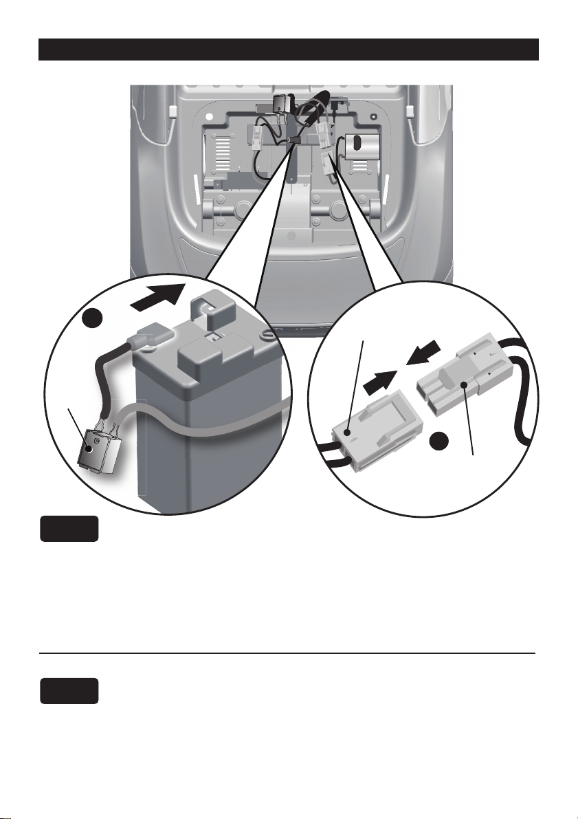
Connect the Power Supply │ 9
Rear Top View
Fuse
box
Battery
Vehicle
connector
Motor connector
1WD
2WD
1. Plug the red fuse connector into the terminal on battery.
2. Plug the vehicle connector into the motor connector on body as shown
above.
1. Plug the red fuse connector into the terminal on battery.
2. Plug the vehicle connector into the motor connector on body as shown
above. Repeat for the other side.
Table des matières


