7
2 e) Light barrier
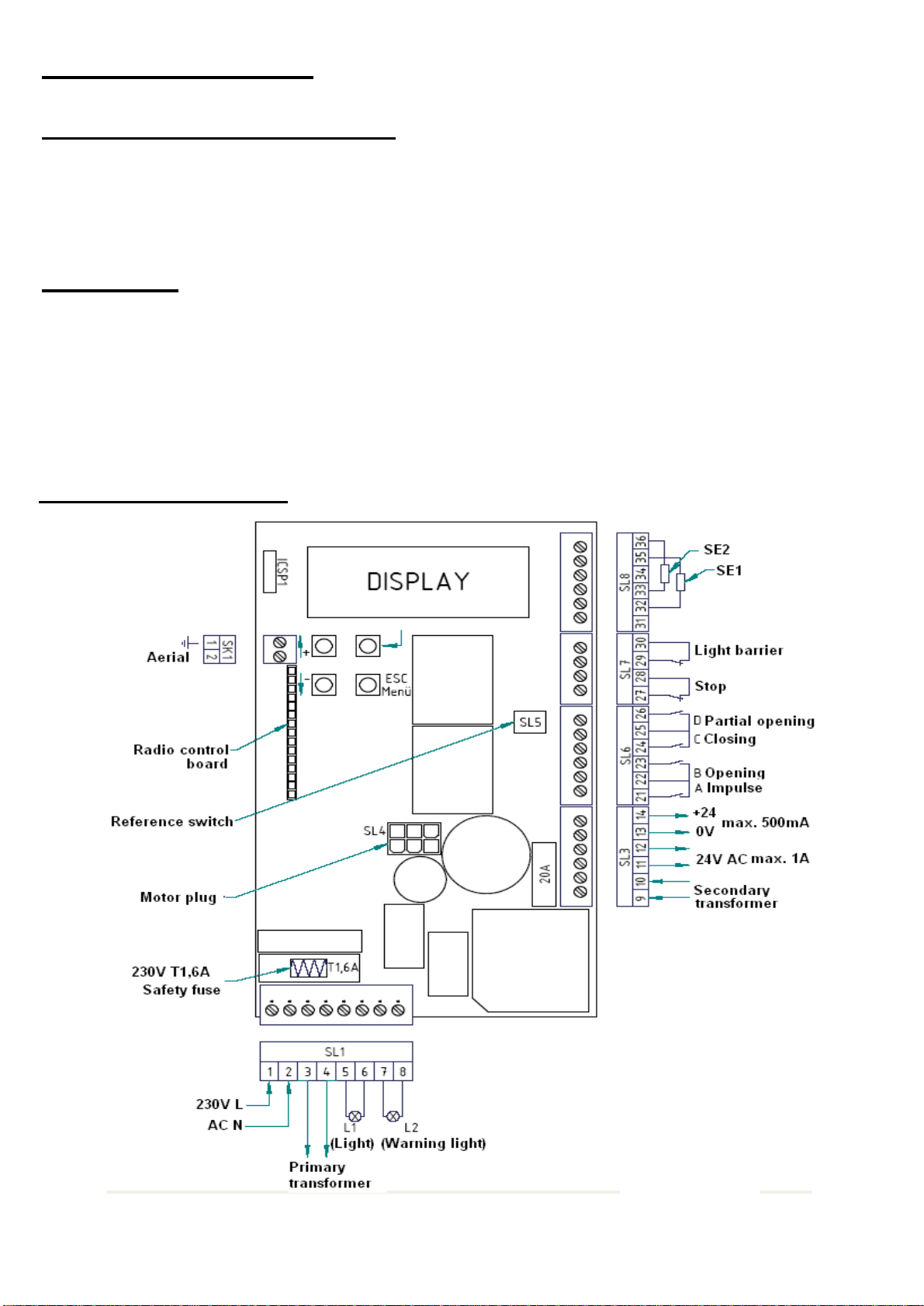
Power supply:
The supply voltage can be tapped from the control board.
Terminal 1+2 =230 AC (mains voltage)
Terminal 11+12 =24V AC (Alternative current – in use of power supply with
transformer)
Terminal 13+14 =24V DC (Direct current)
The potential-free opening contact (closed when inactive) of a light barrier can be
connected to the terminals 29 & 30. Furthermore, it is possible to connect several
safety contact edges. Their potential-free opening contacts must be connected in
series.
Is the operating mode AUTOMATIC CLOSING activated, the gate will close
optionally after the deactivation of the input “closing after leaving the light barrier
with set delay”or “after expiration of the hold-open time”.
External safety devices must be approved for personal safety since their function is
not tested by the control board! The reliability of their performance must be tested at
least every 6 months.
2 f) Stop input / Wicket door
The potential-free opening contact (closed when inactive) of a wicket door and/or of
an emergency stop control can be connected to the terminals 27 & 28.
Furthermore, it is possible to connect several safety devices. Their potential-free
opening contacts must be connected in series.
This safety input is activated in both directions of the gate. When this input is
activated the drive of the gate will not operate or a moving gate will come to an
emergeny stop. CAUTION: In this case no reversing will be operated and disable is
activated.
2 g) 8,2kΩ-safety contact edges
It is possible to connect safety contact edges with an 8,2kΩ terminating resistor
between the terminals 32 & 35 and between 33 & 36.
SE1 (closing) (Safety input 1 –terminals 32 & 35)
SE2 (closing) (Safety input 2 –terminals 33 & 36)
External safety devices must be approved for personal safety since their function is
not tested by the control board! The reliability of their performance must be tested at
least every 6 months.