Beijer Electronics BoX2 extreme Manuel utilisateur

Installation Manual
BoX2 base
MAEN274
2023-09

Foreword
All BoX2 devices are developed to satisfy the demands of human-machine communication.
Configuration is carried out on a PC using iX Developer software. The project can then be transferred
and stored in the device itself. Various types of automation equipment such as PLCs, servos or
drives can be connected to the device. In this manual, the term “the controller” refers to the
connected equipment. This manual explains how to install the device. Please refer to the iX
Developer reference manual for further information.
Copyright © 2023 Beijer Electronics AB. All rights reserved.
The information in this document is subject to change without notice and is provided as availa-
ble at the time of printing. Beijer Electronics AB, including all its group companies, reserves
the right to change any information without updating this publication. Beijer Electronics AB, in-
cluding all its group companies, assumes no responsibility for any errors that may appear in this
document. Read the entire installation manual prior to installing and using this equipment. Only
qualified personnel may install, operate or repair this equipment. Beijer Electronics AB, includ-
ing all its group companies, are not responsible for modified, altered or renovated equipment.
Because the equipment has a wide range of applications, users must acquire the appropriate
knowledge to use the equipment properly in their specific applications. Persons responsible
for the application and the equipment must themselves ensure that each application is in
compliance with all relevant requirements, standards and legislation in respect to configuration
and safety. Only parts and accessories manufactured according to specifications set by Beijer
Electronics AB, including all its group companies, may be used.
BEIJER ELECTRONICS AB, INCLUDING ALL ITS GROUP COMPANIES, SHALL NOT BE LIABLE TO
ANYONE FOR ANY DIRECT, INDIRECT, SPECIAL, INCIDENTAL OR CONSEQUENTIAL DAMAGES RESULT-
ING FROM THE INSTALLATION, USE OR REPAIR OF THIS EQUIPMENT, WHETHER ARISING IN TORT,
CONTRACT, OR OTHERWISE. BUYER'S SOLE REMEDY SHALL BE THE REPAIR, REPLACEMENT, OR
REFUND OF PURCHASE PRICE, AND THE CHOICE OF THE APPLICABLE REMEDY SHALL BE AT THE
SOLE DISCRETION OF BEIJER ELECTRONICS AB, INCLUDING ALL ITS GROUP COMPANIES.
Head Office
Beijer Electronics AB
Box 426
201 24 Malmö, Sweden
www.beijerelectronics.com / +46 40 358600

Table of Contents
1. Safety Precautions ........................................................................................ 5
1.1. General ............................................................................................ 5
1.2. Hazardous Materials ............................................................................. 5
1.3. Disposal Requirements Under WEEE Regulations ............................................ 5
1.4. UL and cUL Installation .......................................................................... 6
1.5. During Installation ................................................................................ 6
1.6. During Use ......................................................................................... 7
1.7. Service and Maintenance ........................................................................ 7
1.8. Dismantling and Scrapping ...................................................................... 7
2. Installation ................................................................................................. 8
2.1. Installation Process .............................................................................. 8
2.1.1. Connections to the Controller ......................................................... 9
2.1.2. Other Connections and Peripherals ................................................... 9
3. Technical Data ............................................................................................ 10
4. Chemical Resistance ..................................................................................... 12
4.1. Plastic Casing .................................................................................... 12
5. Device Drawings .......................................................................................... 13
5.1. Connectors ....................................................................................... 13
5.1.1. Communication Ports .................................................................. 13
5.2. Device Outline ................................................................................... 14
6. Additional Installation Tips ............................................................................. 15
6.1. Grounding the Device ........................................................................... 15
6.2. Ethernet Connection for the Device .......................................................... 16
6.3. To Achieve Better EMC Protection ............................................................ 16
6.4. Ambient Temperature .......................................................................... 17
6.5. Safety ............................................................................................. 19
6.6. Galvanic Isolation ............................................................................... 20
6.7. Cable and Bus Termination RS-485 ........................................................... 20
6.8. USB Flash Drive .................................................................................. 21
Beijer Electronics, MAEN274 3 2023-09

4
1. Safety Precautions
Both the installer and users of the BoX2 device must read and understand this manual.
1.1. General
• Read the safety precautions carefully.
• Check the delivery for transportation damage. If damage is found, notify the supplier as soon as
possible.
• Do not use the device in an environment with high explosive hazards.
• The supplier is not responsible for modified, altered, or reconstructed equipment.
• Use only parts and accessories manufactured according to specifications of the supplier.
• Read the installation and operating instructions carefully before installing, using, or repairing the
device.
• Never allow fluids, metal filings or wiring debris to enter any openings in the device. This may
cause fire or electrical shock.
• Only qualified personnel may operate the device.
• This is an OPEN-TYPE device and should therefore be installed in an enclosure to prevent
unqualified personnel from operating it.
• The figures in this manual serve an illustrative purpose. Because of the many variables associated
with any particular installation, the supplier cannot assume responsibility for actual use based on
the figures.
• The supplier neither guarantees that the device is suitable for your particular application, nor
assumes responsibility for your product design, installation or operation.
1.2. Hazardous Materials
Part description
零件描述
Toxic and hazardous materials or elements
有毒和有害的材料或元素
PCB and electronic components
PCB 和电子元件
Pb Hg Cd Cr6+ PBB PBDE
X O O O O O
O: Indicates that the concentration of the hazardous substance in all homogeneous materials in the
parts is below the relevant threshold of the GB/T 26572-2011 standard.
O: 表示该有害物质在该部件所有均质材料中的含量均在 GB/T 26572-2011 规定的限 量要求以下。
X: Indicates that the concentration of the hazardous substance of at least one of all homogeneous
materials in the parts is above the relevant threshold of the GB/T 26572-2011 standard. But still
complies with the EU RoHS Directive 2011/65/EU.
X: 表明该有害物质至少在部件的某一均质材料中的含量超出 GB/T 26572-2011 规定 的限量要求。但仍然
符合 EU RoHS 指令 2011/65/EU。
1.3. Disposal Requirements Under WEEE Regulations
For professional users in the European Union: If you wish to discard electrical and electronic
equipment (EEE), please contact your dealer or supplier for further information.
For disposal in countries outside of the European Union: If you wish to discard this product please
contact your local authorities or dealer and ask for the correct method of disposal.
Safety Precautions
Beijer Electronics, MAEN274 5 2023-09
1.4. UL and cUL Installation
WARNING
• Only UL and cUL approved expansion units are allowed to be connected to the
port designated “EXPANSION”. At the moment there are no such units evaluated or
allowed.
SEULES LES UNITÉS D'EXTENSION CERTIFIÉES UL ET cUL PEUVENT ÊTRE RACCORDÉES
AU PORT DÉSIGNÉ «EXPANSION». À L'HEURE ACTUELLE, AUCUNE UNITÉ DE CE TYPE
N'A ÉTÉ TESTÉE OU AUTORISÉE.
• Explosion hazard! Substitution of components may impair suitability for Class I,
Division 2.
RISQUE D’EXPLOSION! LA SUBSTITUTION DE COMPOSANTS PEUT NUIRE Á LA
CONFORMITÉ DE CLASSE I, DIVISION 2.
• Battery may explode if mistreated. Do not recharge, disassemble or dispose of in
fire.
LA BATTERIE PEUT EXPLOSER EN CAS DE MAUVAISE MANIPULATION. NE LA
RECHARGEZ PAS, NE LA DÉMONTEZ PAS ET NE LA JETEZ PAS DANS LE FEU.
• This product contains a battery; this must only be changed in an area known to be non-hazardous.
• Replace the battery with a BR2032 battery. Use of another type of battery may present a risk of
fire or explosion.
• For use on a flat surface of a type 4X enclosure indoor use only.
• Use minimum 75°C copper conductors only.
• To make wiring connections to the power supply connector, follow the table with cable and torque
specifications below:
Terminal Block Connector Wire Size AWG Torque (Lb.In.)
X1/X100 Phoenix connectors AWG 30 – 12 5 – 7
X1/X100 Anytek connectors AWG 24 – 12 3.5
X1/X100 DECA connectors AWG 24 – 12 7
• These devices are Class 2 supplied programmable controllers (industrial PCs) for the use in
industrial control equipment and are intended to be (front) panel mounted (Type 12 and 4x for
indoor use only).
CAUTION
The enclosure provides a degree of protection of at least IP20, but when installed in
an apparatus, it should meet IP65.
LE BOÎTIER OFFRE UN DEGRÉ DE PROTECTION D'AU MOINS IP20, MAIS LORSQU'IL EST
INSTALLÉ DANS UN APPAREIL, IL DOIT ÊTRE DE CLASSE IP65.
1.5. During Installation
• Install the device according to the accompanying installation instructions.
• Ground the device according to the accompanying installation instructions.
Safety Precautions
2023-09 6 Beijer Electronics, MAEN274

• Only qualified personnel may install the device.
• Separate the high voltage, signal, and supply cables.
• Make sure that the voltage and polarity of the power source is correct before connecting the
device to the power outlet.
• Peripheral equipment must be appropriate for the application and location.
1.6. During Use
• Keep the device clean.
• Emergency stop and other safety functions may not be controlled from the device.
1.7. Service and Maintenance
• Only qualified personnel should carry out repairs.
• The agreed warranty applies.
• Before carrying out any cleaning or maintenance operations, disconnect the equipment from the
electrical supply.
• The battery must be replaced by an authorized Beijer Electronics service center.
1.8. Dismantling and Scrapping
• Recycle the device and parts of it according to local regulations.
• The following components contain substances that might be hazardous to health and the
environment: lithium battery and electrolytic capacitor.
Safety Precautions
Beijer Electronics, MAEN274 7 2023-09
2. Installation
2.1. Installation Process
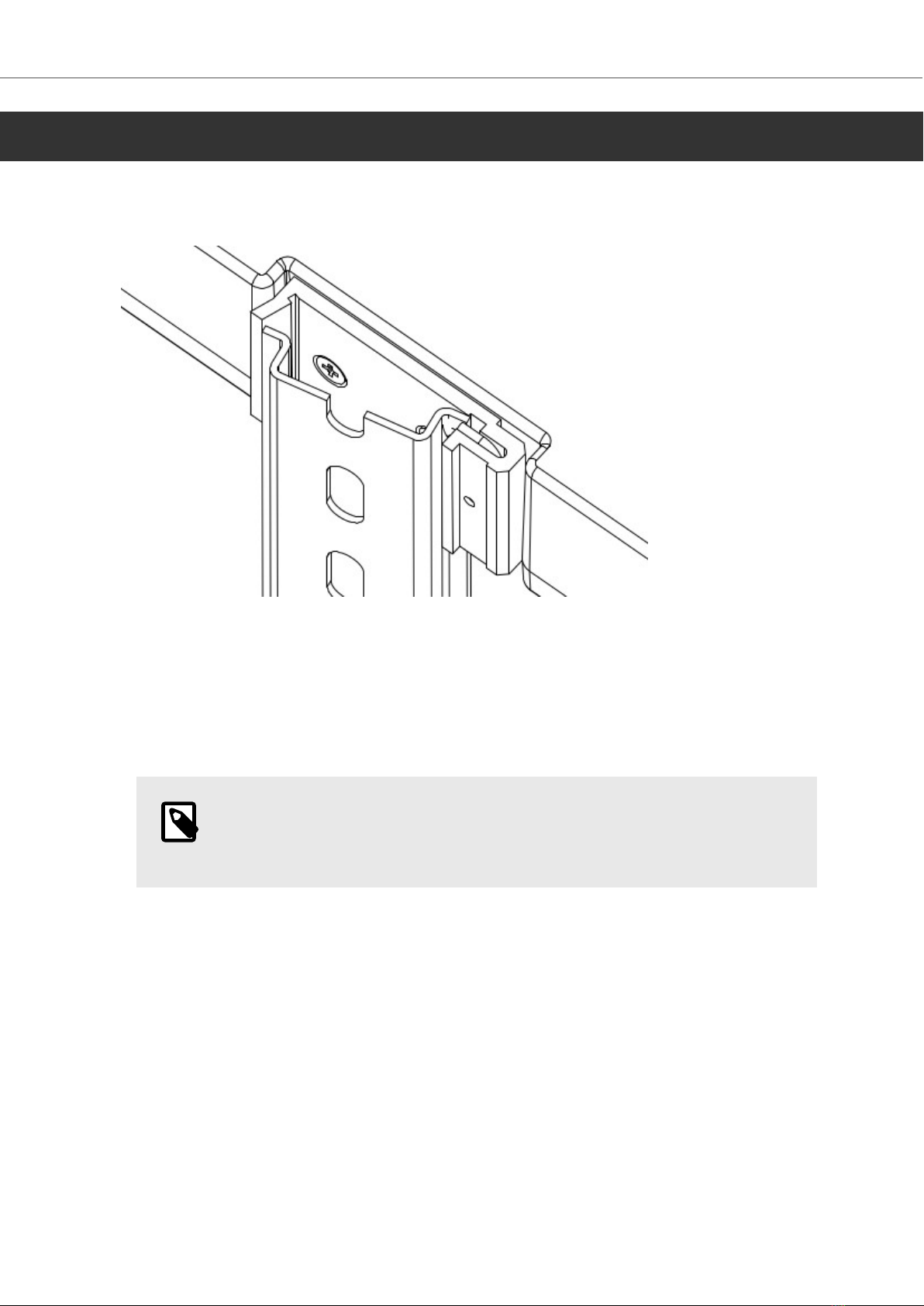
The BoX2 device can be used as a bench top device or clipped onto a DIN rail.
The following is needed:
• No tools required - standard usage.
Do the following:
1. Unpack and check the delivery. If damage is found, notify the supplier.
NOTE
Place the device on a stable surface during installation. Dropping the device or
letting it fall may cause damage.
2. Connect the cables in the specified order, according to the following drawing and steps.
Installation
2023-09 8 Beijer Electronics, MAEN274
24V DC
RS232/
RS422/
RS485
24V DC
A
D
Controller
Power
B
Ethernet
C
The image is illustrative only and may differ slightly from the actual device.
• Connect cable A.
• Connect cable B, using 14-20 AWG (2.08–0.52 mm2), 180–220 N-cm torque.
• Connect cable C.
• Connect cable D. The recommended cross-section of the cable is 1.5 mm2.
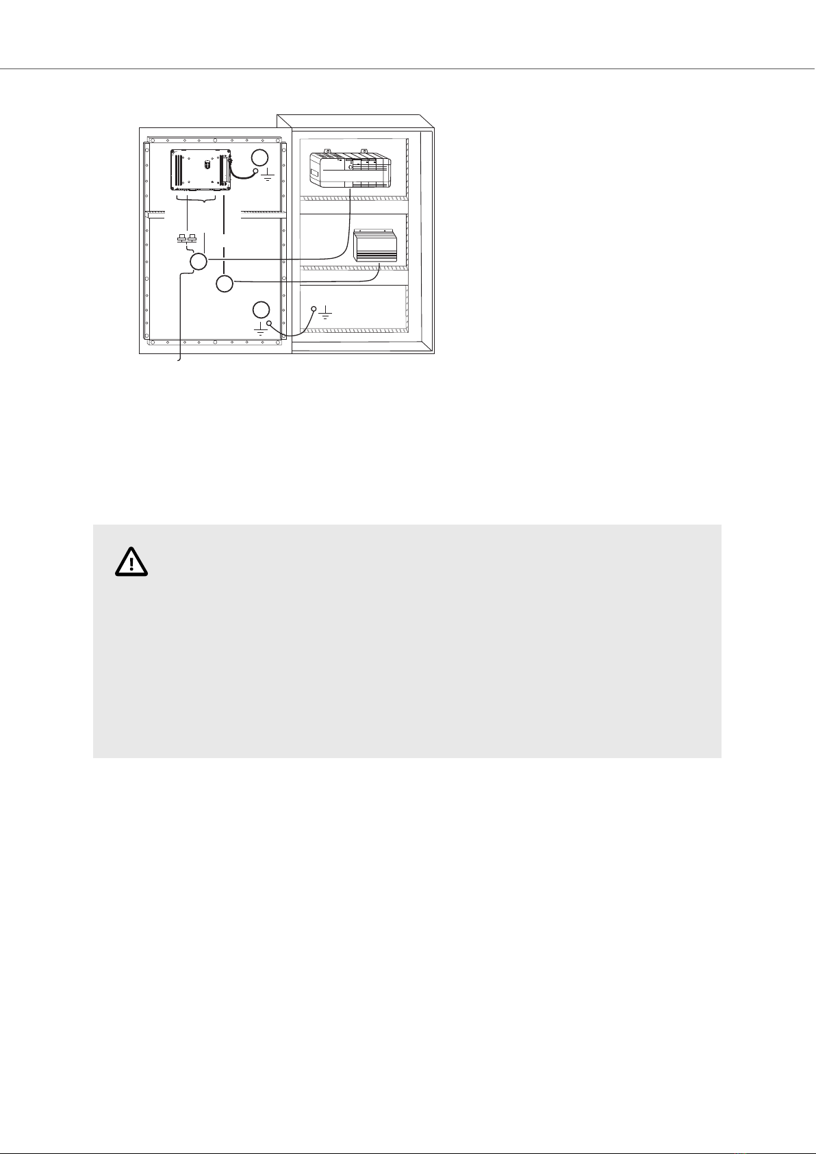
CAUTION
• The device must be brought to ambient temperature before it is started up. If
condensation forms, ensure that the device is dry before connecting it to the
power outlet.
• Ensure that the device and the controller system have the same electrical
grounding (reference voltage level), otherwise errors in communication may occur.
• Ensure that the voltage and polarity of the power source is correct.
• Separate high voltage cables from signal and supply cables.
• Shielded communication cables are recommended.
2.1.1. Connections to the Controller
For information about the cables to be used when connecting the device to the controller, please
refer to the help file for the driver in question or see section Cables.
2.1.2. Other Connections and Peripherals
Cables, peripheral equipment and accessories must be suitable for the application and its
environment. For further details or recommendations, please refer to the supplier.
Installation
Beijer Electronics, MAEN274 9 2023-09

3. Technical Data
Parameter BoX2 base
Front panel, W×H×D 130 × 89 × 35 mm
Standalone mounting VESA 75 × 75
Note: Maximum screw length for VESA mounting is 4 mm. Usage of
longer screws may lead to damage.
Sealing IP20
Frame material Plastic (PC+ABS)
Weight 0.3 kg
CPU 400 MHz ARM9
Serial port COM A Standard D-sub (9 Pin, female)
COM1: 1×RS-232 Rx/Tx with RTS/CTS
COM2: 1×RS-422 or 1×RS-485 or 1×CAN2.0B
*Not supported for X2 pro 7/10/15web or X2 extreme 7/12/15 HP
web.
Serial port COM B M12 (8 pin, female)
Standard D-sub (9 Pin, female)
COM3: 1×RS-232 Rx/Tx with RTS/CTS
COM4: 1×RS-485
*Not supported for X2 control 7/10/15 web or X2 extreme 7/12/15
HP web.
Ethernet 10/100 Mbit Base-T (shielded RJ45 with LEDs)
USB Supports up to USB 2.0 High Speed
Flash memory
(application memory)
256 MB SSD (NAND Flash)
Application memory 200 MB
Memory RAM 128 MB (DDR2)
NVRAM N/A
Real time clock Yes
Battery Lithium ion, 3V / 200mAh
Power consumption at
rated voltage
3 W
Fuse Internal DC fuse, 2.0 AT
Power supply CE: The power supply must conform with the requirements
according to EN/IEC 60950 and EN/IEC 61558-2-4.
UL and cUL: The power supply must conform with the requirements
for class 2 power supplies.
Operating temperature -10°C to +50°C
Storage temperature -20°C to +60°C
Relative humidity in
operation
5 - 85% non-condensation
Technical Data
2023-09 10 Beijer Electronics, MAEN274
Autres manuels pour BoX2 extreme
2
Table des matières
Autres manuels Beijer Electronics Convertisseur de média

Beijer Electronics
Beijer Electronics BoX2 base v2 Feuille d'instructions

Beijer Electronics
Beijer Electronics BoX2 pro Manuel utilisateur

Beijer Electronics
Beijer Electronics BoX2 extreme Manuel utilisateur

Beijer Electronics
Beijer Electronics 100-0973 Manuel utilisateur

Beijer Electronics
Beijer Electronics JetCon 1701GP-U Manuel utilisateur


