BEC Integrated Solutions NT-IP-A9K Mode d'emploi

BEC
NT-IP-DRS1
Integrated Solutions
BEC Integrated Solutions - Williamsville, New York - 716-689-0871
Video Entry System
IP Video Intercom
2017
Installation Manual
and Programming Guide

Table of Contents
1
Technical Specications................................................................2
Installation...............................................................................3-7
Conguration & Screenshots
NT-IP-G9W Monitor......................................................10-19
NT-IP-A9K Door Panel...............................................20-24
NT-IP-DRG/DRS1/DRCR....................................24-25
Troubleshooting........................................................................26
Warranty.....................................................................................26
Contact Us.......................................................................................27
5225 Sheridan Drive
Georgetown Square
Williamsville, NY 14221
Phone: 1-716-689-0871
Toll-Free: 1-888-556-3998
E-Mail: [email protected]
http://www.becintegrated.com
Copyright © 2017 BEC Integrated Solutions LLC.
IP Video Intercom

2
Outdoor Panel Functions
• Video Intercom with Indoor Monitors and optional management center
• Optional IC/ID/RF card reader
(A9K & DRCR Only) (max # of fobs = 10,000pcs)
• Passcode Entry
(A9K Only)
• Supports SIP 2.0 Protocol to communicate with IP phone and SIP software
• Infrared Detection
NT-IP-A9K
• Operating Voltage: 12V DC
• Power: 6W - Operating | 3W - Standby
• Display: 4.3” TFT LCD (480x272)
• IP Rating: IP-54
• Dimensions: 6.1” (W) x 14.76” (H) x 2.05” (D)
• Operating Temperature: 14°F~131°F
• Operating Voltage: 12V DC
• Power: 5W (Operating)/2.5W
(Standby) POE Ready
• IP Rating: IP-55
• Dimensions: 3.94” (W) x 6.30”
(H) x 1.85” (D)
• Operating Temperature: -40°F
~ 158°F
• Operating Voltage: 12V DC
• Power: 5W (Operating)/2.5W (Stand-
by) POE Ready
• IP Rating: IP-55
• Dimensions: 3.94”(W) x 6.30”(H) x
1.85”(D)
• Operating Temperature: -40°F ~
158°F
• Operating Voltage: 12V DC
• Power: 5W (Operating)/2.5W
(Standby) POE Ready
• IP Rating: IP-65
• Dimensions: 4.57”(W) x 7.56”(H)
x 1.85”(D)
• Operating Temperature:
14°F~131°F
Technical Specications
Entry Panels
NT-IP-DRG NT-IP-DRS1 NT-IP-DRCR

3
Installation
NT-IP-A9K
Tech Specs Cont’d
Monitor
Monitor Features
• VOIP: Supports audio/video calling over IP networks, monitoring network door panels & cameras, and
call logging.
• Security: Supports up to 8 alarm zones with 3 states, with built-in zone/scene setup.
• Smart-Home: Can interface with a smart-home system via RS-485 communication.
• Android Features: Ability to install apps via android APK les.
• Built in Micro-USB port for power & data transfer.
Parts Included:
Punch out
rst for water
drainage
NT-IP-G9W-S &NT-IP-G9W
• Operating Voltage: 12V DC (POE)
• Power: 6W (Operating)/2.5W (Standby)
• Screen Size: 7” @ 1024x600 Resolution
• Dimensions: 9.25” (W) x 5.71” (H) x 0.77” (D)
• OS: Android 4.4 KitKat
• Internal Storage: 4GB
• SD Card Maximum: 32GB
Model NT-IP-G9W-S includes
BEC SIP Server Access
*************
*************

4
Installation Cont’d
A9K Connections & Wiring
Rear
Connections Standard Lock Control Signal
RS485 Interface
Card Reader Interface
Switching Value Lock Wiring
Door Detection & Exit Switch
Notes:
• The standard control signal can be used with an
Altronix 6062 relay to handle the lock connections
with any lock 9-24vDC or AC.
• The switching value connection supports a max cur-
rent of 3.5A and requires an external PSU for your
lock. When the outside power is off, the NO and NC
terminals are opposite from normal operation.
• The optional RS485 header enables connections be-
tween compatibile equipment. Capable of 12v/100mA
power output.
• Exit/Door Detection header allows for an internal
exit switch and a sensor to know when the door is
open or closed.
• The card reader interface can read keyfobs from a
standalone controller. If unit has reader built-in, it
cannot be used.

5
Installation Cont’d
Parts Included:
Rear
Connections:
Punch out bottom
hole rst for water
drainage
Drain
Back-box
NT-IP-DRG NT-IP-DRS1

A Note on Lock Wiring
All IP door panels are designed to operate an electric strike, available as a “slim-style” 12vDC strike plate
from BEC, however any type of lock can be used if wired to the dry contacts on an Altronix 6062 relay, also
available from BEC. You must include an external power source for your lock. If you need assistance
with lock wiring, please contact either BEC technical support, or your lock manufacturer for further support.
6
Installation Cont’d
Parts Included:
NT-IP-DRCR
Name Tag
Screw Holes
Back-Box
Drain
Punch out bottom hole rst
for water drainage Name Tag
Cover
To indoor
building-exit button
C
NC
NO

Speaker
Micro-USB
Port
Camera
(Optional)
SD Card
Microphone
Talk (Answer)
(Reserved)
Call Guard Station
Monitor
Unlock
7
Installation Cont’d
Connections & Wiring
Home Automation
Security Integration
Alarm
Audio Extension
NT-IP-G9W-S & NT-IP-G9W

8
General System Diagram
9
Features & Set-Up
Quick Overview
Before setting up your system, consider the amount of time it would take you to go room-to-room to program
your monitors. In a large environment with many monitors, it may be extremely time-consuming to
program on-site. In this case, we recommend setting up all monitors locally, one-at-a-time, then installing
them in their assigned rooms. This ensures, not only will the monitors be plug-and-play at that point, but you’ll
have an understanding of the basic system functionality, before your scheduled installation date.
To begin, you’ll need to set the IP address of each monitor and door panel either at each component, or
through a network connected computer using the default IP: 192.168.68.90 for each device, one-at-a-time.
*NOTE*: You’ll have conicting IP addresses out of the box if more than one deviced is connected to the
network.
Once addressed, you’ll need a laptop or computer connected at the switch, or within your network to
access the online settings. To access your online settings out of the box, you’ll need to set the PC’s ethernet
controller’s IPv4 address. Assign the PC’s IP to 192.168.68.xxx (x=# of your choice), with a default gateway
of 192.168.68.1. You can then type in the IP address in a browser window of your choice, enter the admin
credentials (default=admin:123456),then adjust settings using the device’s graphical user interface (GUI).
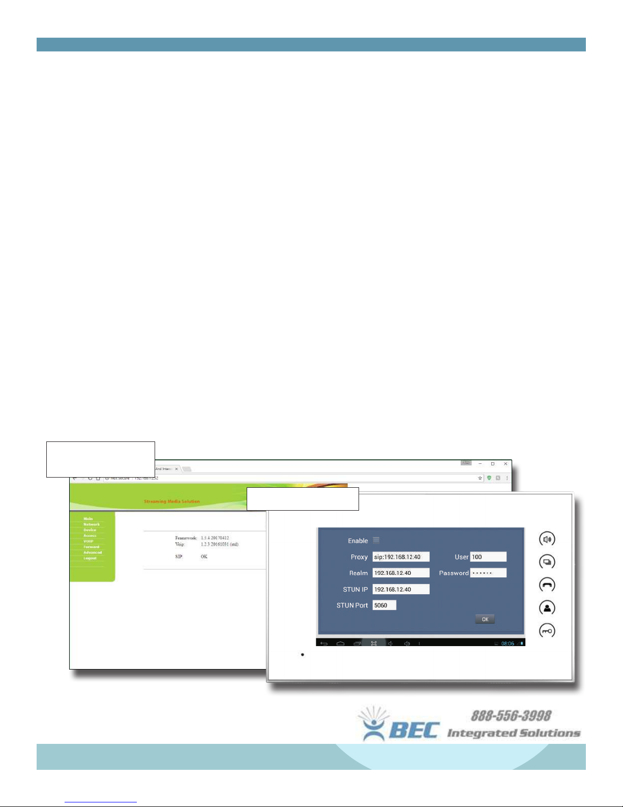
Note: All door stations, except the full-sized A9K model, must be programmed over the network.
Door Station Main Page
(A9K)
Monitor Network Settings
Ce manuel convient aux modèles suivants
5
Table des matières
Autres manuels BEC Integrated Solutions Système d'interphone


