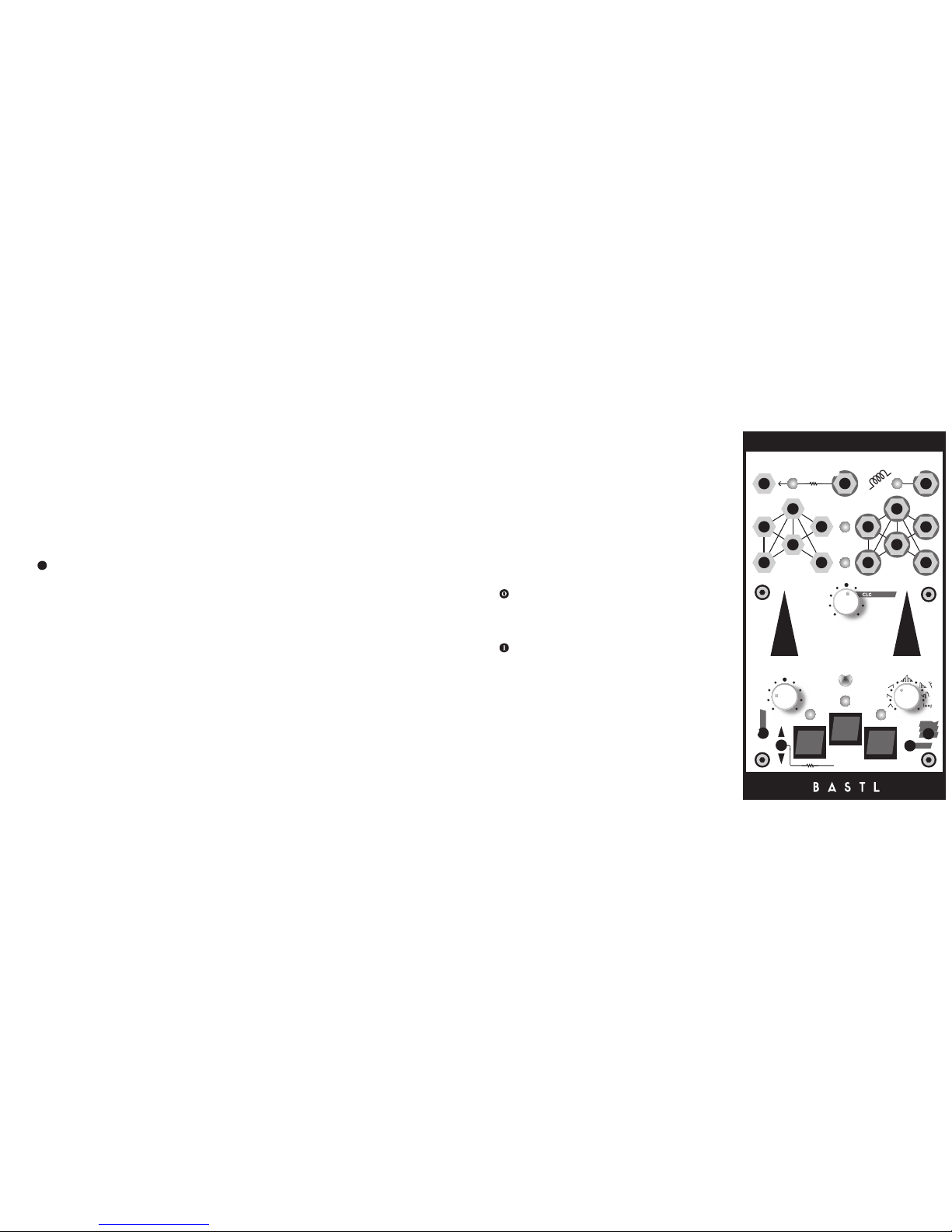
6
tmodultion chnnels
CV input nd CV output per chnnel
select OUT outputs current selected modultion
chnnel
indiction LED for select OUT
ech chnnel cn be either AUTOMATION, LFO or ADSR
AUTOMATION: clocked 32 step memory with djustble
liner interpoltion, number of steps nd possibility of
independent clocking
LFO: rte, XOR wveshpe, shpe (rmp, inverted
rmp, tringle, flopping rmp, flopping tringle, stepped
rndom with smoothing nd looping), synchronistion
with clock
ADSR: ttck, sustin , decy set to sme vlue s
relese, liner or exponentil, looping mode, ttck-hold-
relese mode
jumpers to select 0— 5V or 0—10V rnge for ech CV
input
clock input
clock genertor output normlized to clock input
AUTOMATION
Automtion is 32 step knob recorder with djustble
mount of liner interpoltion. Hold the record button
nd use the TOP knob to enter voltges into the memory.
Pulse signl on Clock input dvnces to next step. The
LEFT knob djusts the mount of smoothing. When it is
fully to the left, the signl is stepped nd when fully right
it is linerly interpolted. The RIGHT knob djusts how
mny of 32 steps re used.
Holding the FN button nd pressing the big SELECT
buttons gives you ccess to more settings. The leftmost
big button sets whether the utomtion is clocked by
themster clock (light ON) or if it is expecting clock
on the selected chnnel input (light OFF). The middle
big button clers the whole memory to 0 volts. The
rightmost big button selects whether the number of
steps set by the RIGHT knob llows ny number including
odd numbers or if it filters them out nd lets you set the
number of steps only to 1,2,4,8,16 or 32 steps.
LFO
LFO is n dvnced low frequency oscilltor with
wveshper nd mny extr fetures including loopble
clocked rndom genertor with smoothing.
In the defult settings, the TOP knob sets the LFO rte.
In synchronistion mode it sets the divider of the clock
input to which the LFO will synchronise nd in pingble
mode it sets the reltive phse shift of the ping input
clock.
The RIGHT knob selects the wveform/ type of the LFO.
In order from leftmost to rightmost the wveforms re:
tringle, sw, rmp, flopping tringle, flopping sw,
stepped rndom, looped stepped rndom. The stepped
rndom mode is either clocked by the LFO rte, or by the
divider of the clock input, when in synchronistion mode.
The looped stepped rndom mode tkes the lst 32 steps
of the stepped rndom pttern nd loops them.
features
The LEFT knob sets wveshping or smoothing for the
stepped rndom wve. For rmp wveform it cts s
bit reducer nd for the stepped rndom wve it works
s smoothing. For ll other wveforms it cts s XOR
modultion. This mens tht the wveform is XORed with
number from 0-255 set by this knob. XORing with 255
inverts the wveform.
Holding the FN button nd pressing the big SELECT
buttons gives you ccess to the following settings.
The leftmost big button sets whether the LFO is free
running (light OFF) or synchronised to the min CLK
IN. When synchronised, the TOP knob sets the divider
specifying how mny clock pulses one LFO period should
lst. The leftmost chnnels synchronize with no phse
offset to the clock, the middle chnnels synchronize with
90°phse shift nd the leftmost chnnels synchronize
with 180°phse shift. This cn be used for vrious
qudrture effects.
The middle big button sets whether the CV input is
ffecting the LFO rte proportionlly with the voltge on
tht input (light OFF) or if it works in pingble mode. This
mens tht if you send t lest two pulses to this input,
the LFO sets its rte to the time in between these pulses.
When this setting is ctivted the synchronistion to the
min clock is dectivted nd the TOP knob ffects the
phse shift reltive to the clock on CV input.
The rightmost big button selects the rnge of the LFO. It cn
be slow with periods in the rnge of 2 min to 200ms (light
off) of fst: 2 s -10 ms. This pplies only to the free running
LFO (both middle nd leftmost lights re turned OFF).
ADSR
ADSR uses the CV input s GATE input for triggering
the envelope. The TOP knob sets ttck (1ms—10s). The
LEFT knob sets sustin or hold time, when in hold mode
(1ms —10s). The RIGHT knob sets both decy nd relese
time (1ms — 10s).
Holding the FN button nd pressing the big SELECT
buttons gives you ccess to more settings. The leftmost
big button cn turn on HOLD mode (light ON). In hold
mode, the envelope is in ttck - hold - relese mode.
Theenvelope resets the full cycle nytime there is rising
edge from clock pulse t the GATE input.
The middle big button sets whether the envelope is in
LOOP mode (light ON). In the this mode, the GATE input
resets the envelope cycle.
The rightmost big button selects whether the envelope
isliner (light ON) or exponentil (light OFF).
Red
Green
Blue
Take it Carefull
CV5 CV2CV3CV6 CV4 CV1
BASTL-INSTRUMENTS.com
designed and produced in czech republic
red
GND +12 +5-12
POWER
jumper = 0-5V range
no jumper = 0-10V range
disconnect for programming
program top
exp D2-prot
program bottom
!
P C B