Basalte B.link Manuel utilisateur
B.link
Manual
1 / 32 v.1.1 © 2014 basalte
B.link
Manual
basalte bvba
hundelgemsesteenweg 1a
9820 merelbeke
belgium

B.link
Manual
2 / 32 v.1.1 © 2014 basalte
Table of Content
1. Introduction ............................................................................................................................. 3
2. Installation ............................................................................................................................... 4
3. Configure the B.link in ETS ...................................................................................................... 5
3.1 IP configuration ................................................................................................................... 5
3.2 Surround receivers ..............................................................................................................
3.3 KNX Input Objects ................................................................................................................ 7
3.4 KNX Output Objects ............................................................................................................. 8
4. B.link Flex ................................................................................................................................. 9
4.1 Installation and Initial Connectivity ..................................................................................... 9
4.2 Configuration ..................................................................................................................... 10
5. B.link Configuration software ................................................................................................ 14
5.1 Infrared Codes ................................................................................................................... 15
5.2 Serial Codes ....................................................................................................................... 24
5.3 Topology ............................................................................................................................ 25
5.4 Commands ......................................................................................................................... 27

B.link
Manual
3 / 32 v.1.1 © 2014 basalte
1. Introduction
The B.link solution offers a flexible wa to integrate an Audio / Video (A/V) device in a KNX
s stem. Surround receivers, CD pla ers, tuners or digital set top boxes, all become part of the
Asano s stem.
The B.link offers the following KN integration features:
• An Infrared or Serial RS-232 device can be controlled from KNX, using the B.link in
combination with the B.link Flex modules. The B.link Flex modules receive the instructions
from B.link over IP and convert them into IR or Serial signals.
• A/V surround receivers can be integrated directl over IP. With B.link, power on/off, source
selection and volume control with full feedback can be controlled with KNX commands.
B.link directl supports network enabled receivers from Pioneer, Marantz and Denon.
• B.link can also send KNX commands, which can be used in macros and allows to convert
between KNX Data t pes (eg. 1 bit to 1 b tes value).
• B.link allows ou to create macros that include sending out KNX-commands in combination
with IR and serial instructions. These macros make it possible to create powerful scenarios.
One B.link can be connected to 16 B.link Flex modules over IP, with each module able to control
either 3 IR or 1 serial device. In addition to the 16 B.link Flex modules, the B.link can also connect
to 3 A/V surround receives
1
directl over IP.
The B.link uses ETS for configuring the following settings:
• IP networking parameters
• A/V Surround receivers controlled directl over IP (maximum 3 receivers)
• Input objects, used to trigger one or a sequence of IR, Serial or KNX commands
o 50 1-bit input objects
o 50 1-b te input objects
o 20 4-bit input objects
• Output objects, used to integrate KNX command in scenarios (eg. Scene selection, blinds
control):
o 50 1-bit output objects
o 50 1-b te output objects
o 5 14-b te output objects
In addition to ETS, the powerful B.link Configuration software allows to configure the
integration with IR and serial devices through the B.link Flex modules. The B.link tool also
simplifies definition of scenarios b creating macros sending out a sequence of IR, serial and KNX
instructions.
1
Currentl support for Pioneer, Marantz and Denon

B.link
Manual
4 / 32 v.1.1 © 2014 basalte
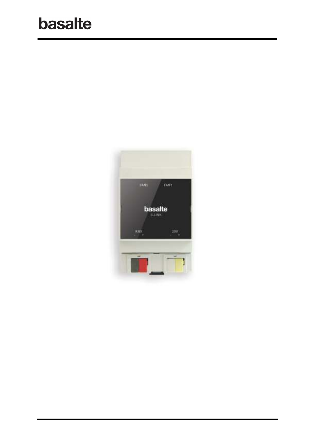
2. Installation
After mounting the B.link in a standard DIN rail, install the B.link b :
• connecting the B.link to the KNX network;
• connecting the B.link to our local network. The B.link has an integrated switch with a
second Ethernet port that can be used to dais chain other network modules such as MMS
modules or additional B.link modules;
• power the B.link using 29V DC power suppl .
The B.link communicates with the B.link Flex modules and the A/V receivers over TCP/IP.
Therefore all components should be connected to the same local network and configured with a
fixed IP address. For both the A/V receivers and the B.link Flex modules DHCP must be
disabled and a fixed IP address assigned.

B.link
Manual
5 / 32 v.1.1 © 2014 basalte
3. Configure the B.link in ETS
The B.link network parameters, A/V receivers controlled directl b B.link over IP and the KNX
input/output objects are configured using ETS.
The B.link comes with a configuration software that allows ou to configure our own set of IR- and
serial codes, to define the project topolog and to create macros (see chapter 5 B.link
Configuration software).
3.1 IP configuration
The B.link network settings need to be specified in the section IP configuration:
• IP address of B.link
• IP address of the gatewa
• Subnet mask
Parameter Description
IP address of B.link This parameter defines the static IP address of the B.link
Gatewa This parameter sets the IP address of the network default
gatewa (router).
Subnet Mask
This parameter defines the subnet mask used.

B.link
Manual
6 / 32 v.1.1 © 2014 basalte
3.2 Surround receivers
B.link can control up to three surround receivers directly over IP without the need for B.link
Flex module. The network enabled surround receivers from Pioneer, Marantz and Denon are
supported, configuration is done using ETS and do not require the B.link configuration tool.
Parameter Description
Surround receiver brand Select the corresponding brand of surround receiver
1 = Pioneer
2 = Denon
3 = Marantz
Ramp time (0-100%) This parameter defines the time to set the volume from the
minimum to the maximum.
This ramp time should be set identical to the ramp time
defined in the modules controlling the music volume.
For instance, when using a Deseo to control the volume
with slider feedback, the ramp time of the Deseo must be
equal to the ramp time in the B.link.
Settings
From 3 sec to 12 sec with steps of 0.5 sec (default 6 seconds)

B.link
Manual
7 / 32 v.1.1 © 2014 basalte
With the B.link it is possible to switch the receiver on and off, select the source and control the
volume using following KNX objects:
• Receiver on/off 1 bit switching output object
• Receiver on/off feedback 1 bit switching input object
• Receiver source 1 b te value output object
• Receiver source feedback 1 b te value input object
• Receiver volume 1 b te value output object
• Receiver volume feedback 1 b te value input object
• Receiver volume up/down 4 bit ramp up/down object
Important: in order to operate properl , the following configurations must be applied to each
receiver:
• DHCP must be disabled and a static IP address must be configured.
• B default, some surround receivers that are in standb mode cannot be controlled
over the network. In this case, a receiver in standb mode will never switch on
triggered b a KNX command.
Therefore, the receiver should be configured so that network connectivity will
always remain active, even in standby mode.
It’s advised to consult the manual supplied with the receiver to verif and appl the
above configurations, using either the configuration menu or web interface.
• Pioneer: Navigate to the “Network Setup” menu to configure the network functions.
Ensure that the “Network Standb ” is set to ON (ON = AVNavigator can be used
even in standb mode)
• Denon and Marantz: Navigate to the “Network menu” to configure the network
parameters. Ensure that “IP Control” is set to “Alwa s On” (default).
3.3 KN Input Objects
The Input Objects section allows ou to define the input objects used to trigger IR, Serial or KNX
commands. In total, following objects are available:
o 50 1 bit input objects (switching control)
o 50 1 b te input objects (value control)
o 20 4 bits input objects (dimming control)

B.link
Manual
8 / 32 v.1.1 © 2014 basalte
In order to facilitate the KNX programming, it is possible to enable or disable a subset of the
available input objects (per 10 objects).
3.4 KN Output Objects
The “Output Objects” section allows ou to define the outputs objects, that allow the use of KNX
command in the scenarios. In total, the following objects are available:
o 50 1 bit output objects
o 50 1 b te output objects
o 5 14 b te output objects
For the 1-bit and 1-b te output objects it is also possible to enable or disable a set of objects (per
10 objects).

B.link
Manual
9 / 32 v.1.1 © 2014 basalte
4. B.link Flex
The B.link Flex modules, in combination with the B.link module, allows ou to integrate an
Infrared or Serial RS-232 device with KNX . Up to 16 B.link Flex modules can be connected to one
B.link module (over IP). Each Flex module is able to control either 3 IR devices or 1 serial device.
The web interface of the B.link Flex module allows ou to configure:
• Network parameters (static IP address to be used)
• Link port settings for IR or serial configuration
Additionall , the following utilities are provided to support the use of B.link Flex modules:
• Basalte Discovery : This utilit is used to discover B.link Flex modules on the network.
• Basalte Learn : This utilit allows ou to the capture of IR commands and save them in
Global Caché or Hex (CCF) formats.
• Basalte Convert : This executable is used to convert IR codes between Hex and the
Global Caché format.
4.1 Installation and Initial Connectivity
Connect both the Ethernet Network cable and the power suppl or USB to power cable to the B.link
Flex module.
B default, B.link Flex uses DHCP to automaticall obtain an IP address. In case no DHCP server is
present, the default IP address is 192.168.1.70.
The B.link Discovery utility can be used to discover B.link Flex modules. It will listen for the
B.link Flex multicast beacons and displa s their IP address and other details.

B.link
Manual
10 / 32 v.1.1 © 2014 basalte
4.2 Configuration
To configure the B.link Flex, click right on the unit entr in Basalte Discover utilit and click
configure or connect using a browser connecting directl to its IP address.
4.2.1 Network Settings
The following network parameters must be set in the Network Settings:
• Disable DHCP
• Configure the static IP address of the module
• Configure the IP address of the default gatewa
To confirm connectivit to the network, the power LED of the B.link Flex will blink once per second.
Table des matières
Manuels Système de conférence populaires d'autres marques

Kramer
Kramer VIA GO Manuel utilisateur

AVT
AVT MAGIC AC1 Go Manuel utilisateur

ProSoft Technology
ProSoft Technology AN-X4-AB-DHRIO Manuel utilisateur

Sony
Sony PCS-I150 Manuel utilisateur

Middle Atlantic Products
Middle Atlantic Products VTC Series Manuel utilisateur

Prentke Romich Company
Prentke Romich Company Vanguard Plus Mode d’emploi


