Bartington PSU1 Manuel utilisateur

www.bartington.com
INNOVATION IN MAGNETICS
Telephone: +44 (0)1993 706565 •Fax: +44 (0)1993 774813 •Email: [email protected] •Website: www.bartington.com
Bartington Instruments Ltd
5, 8, 10, 11 & 12 Thorney Leys Business Park
Witney, Oxford, OX28 4GE. England
®The copyright of this document is the property of Bartington Instruments Ltd.
Bartington is a registered trademark of Bartington Instruments Limited in the following countries: Australia, Brazil, Canada, China, European Union, India,
Israel, Japan, Mexico, New Zealand, Norway, Russia, Singapore, South Korea, Switzerland, Turkey, United Kingdom, United States of America and Vietnam.
Operation Manual for
PSU1 Power Supply Unit
OM2443/4

BARTINGTON INSTRUMENTS
Page 2 of 18 OM2443/4
Table of Contents
1. About this Manual 3
1.1. Symbols Glossary 3
2. Safe Use 3
3. Introduction to the PSU1 4
4. PSU1 Features 5
4.1. PSU1 Front Panel 5
4.2. Back Panel Connections and Controls 6
5. Compatibility 7
6. PSU1 Operation 7
6.1. Installing and Replacing the Internal Batteries 7
6.2. Initial Charging of the Battery Cells 10
6.3. Location of the Equipment 11
6.3.1. Potentially Hazardous Locations 11
6.3.2. Temperature 11
6.3.3. Proximity to Other Equipment 11
6.4. Connecting the Equipment 12
6.5. Using the PSU1 12
6.5.1. Switching On and Off 12
6.5.2. Filtering 12
6.5.3. Signal Buffering 13
6.6. PSU1 Ratings 13
7. Troubleshooting 14
8. Care and Maintenance 16
8.1. Fuses 16
8.2. Calibration 16
8.3. Cleaning 16
9. End of Life Disposal 17
9.1. Waste Electrical and Electronic Equipment (WEEE) Regulations 17

BARTINGTON INSTRUMENTS
Page 3 of 18 OM2443/4
1. About this Manual
This manual provides the information necessary to help customers install and operate the PSU1.
This manual should also be read in conjunction with the product brochure DS2520 and the unit’s
outline drawing DS2779 can also be found on the product page.
The PSU1 is compatible with a wide range of Bartington Instruments’ magnetometers. The
datasheet and operation of the sensor(s) used should also be read.
Photographs of key components are included, labelled with numbers. A number in the text in
square brackets [ ] refers to that label.
Caution: This manual applies only to the PSU1 Power Supply Unit. For the earlier Mag-
03PSU, please use the manual supplied with that unit or contact Bartington Instruments
1.1. Symbols Glossary
The following symbols used within this manual call your attention to specific types of
information:
WARNING: Indicates a situation in which serious bodily injury or death could result if the
warning is ignored.
Caution: Indicates a situation in which bodily injury or damage to your instrument, or both,
could result if the caution is ignored.
Identifies items that must be disposed of safely to prevent unnecessary damage to the
environment.
Note: Provides useful supporting information on how to make better use of your purchase.
2. Safe Use
WARNING: The PSU1 is fitted with AA size NiMH (Nickel Metal Hydride) rechargeable
batteries. Only AA size rechargeable batteries, which are specified as compatible in the
relevant product brochure, can be used in this product.
WARNING: The fitting of non-approved battery cells may be dangerous. It could affect the
safety of users, damage the equipment and also invalidate the terms and conditions of the
Warranty.

BARTINGTON INSTRUMENTS
Page 4 of 18 OM2443/4
WARNING: The PSU1 can also be powered by mains electricity and contains uninsulated
parts. Ensure that the unit is properly earthed at all times. Only properly trained personnel
should open the unit.
WARNING: These products are not qualified for use in explosive atmospheres or life
support systems. Consult Bartington Instruments for advice.
Note: When operating the PSU1 with the mains charger connected to the unit, it is
necessary to add an inductor over the magnetometer cable to, ensure compliance with BS
EN 55011.
A range of inductors suitable for all cable sizes is available from Bartington Instruments.
The inductor should be positioned as close to the PSU1 end of the cable as possible.
3. Introduction to the PSU1
The PSU1 provides a battery backed power supply of ±12V for most of Bartington Instruments
single and three-axis fluxgate magnetometers. It also contains filters for the analogue outputs of
the sensor. The analogue output are also available on the back panel of the PSU1 on three BNC
connectors for connection to a digital voltmeter or acquisition unit.

BARTINGTON INSTRUMENTS
Page 5 of 18 OM2443/4
4. PSU1 Features
4.1. PSU1 Front Panel
Figure 1. PSU1 Front Panel
1. Magnetometer Output Type Selector Switch
Balanced (button out)
Unbalanced (button pressed in)
Caution: This switch must be set to match your magnetometer output type to ensure
correct results. See the Product Compatibility Charts page on the website .
2. DC/AC Coupling (High Pass Filter (HPF) Control)
DC (button out)
AC (button pressed in)
3. Charge LED
4. On/Off LED
5. On/Off Switch
6. Socket for external charging adaptor
6 5
1 2 3 4

BARTINGTON INSTRUMENTS
Page 6 of 18 OM2443/4
4.2. Back Panel Connections and Controls
Figure 2. PSU1 Back Panel
7. X Signal Conditioned Output.
8. Y Signal Conditioned Output.
9. Z Signal Conditioned Output.
The three BNC connectors carry the conditioned analogue output voltages. The conditioned
outputs are the magnetometer X, Y and Z signals after they have been modified by the low/high
pass filters and, if a balanced output magnetometer is connected, converted to single-ended
signals.
10. Space for unique serial number.
11. Magnetometer socket for the connection of the magnetometer cable.
Note: Ensure correct orientation of the connector (indicated by the cut-out on the
connector body aligning with the notch in the socket).
7 8
11 10
9

BARTINGTON INSTRUMENTS
Page 7 of 18 OM2443/4
5. Compatibility
The PSU1 can operate with the majority of Bartington Instruments single and three-axis fluxgate
magnetometers. The complete list of compatible sensors is available here.
Please note that where the sensors are unpackaged, suitable cables for connection to the PSU1
6. PSU1 Operation
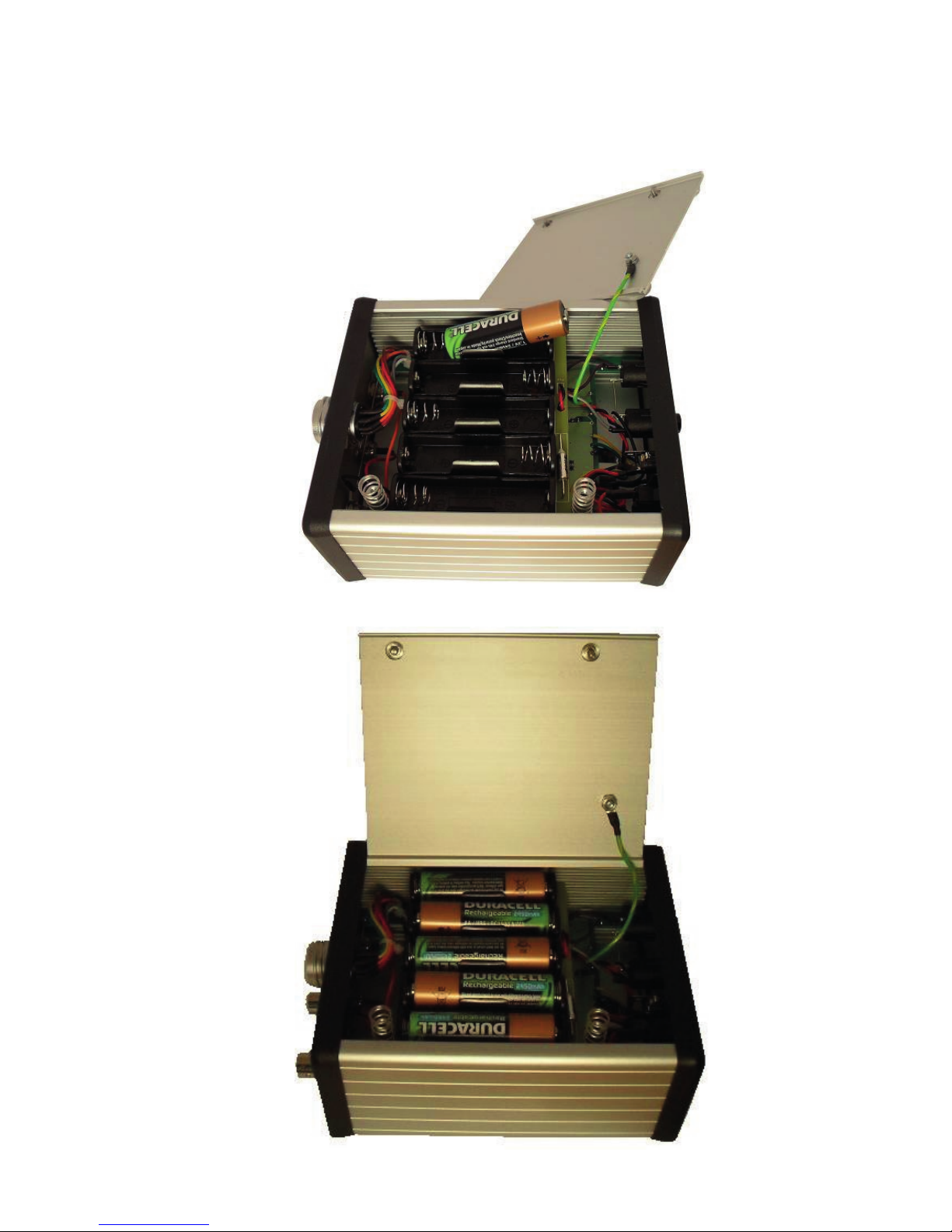
6.1. Installing and Replacing the Internal Batteries
To install the battery cells, or to remove discharged or defective cells, use the following
procedure:
Key:
A – Enclosure lid retaining screw B – Enclosure lid retaining screw
C – Earth lead fixing (do not remove)
AB
C

BARTINGTON INSTRUMENTS
Page 8 of 18 OM2443/4
Place the PSU1 on a suitable surface with the underside facing up and the two enclosure lid
retaining screws nearest to you.
Using a flat-bladed screwdriver of the appropriate size, fully loosen screw A to allow the edge
of the lid to clear the enclosure end cap.
Fully loosen screw B and the lid of the enclosure will lift due to the internal springs.
BARTINGTON INSTRUMENTS
Page 9 of 18 OM2443/4
Lift the lid and place aside to gain access to the battery cell compartment.
Insert each cell into the compartment in turn.

BARTINGTON INSTRUMENTS
Page 10 of 18 OM2443/4
When all 5 cells are in place, locate the back edge of the lid in the enclosure.
A B
Tighten screws A and B in any order.
6.2. Initial Charging of the Battery Cells
To charge the PSU1 batteries, connect the mains charger and switch on the mains supply (if
appropriate). The charging LED [3] will begin to flash indicating that “fast charging” is taking
place. Once the fast charge cycle has completed, the LED will stop flashing and be lit (ON)
continuously, to indicate that “trickle charging” is continuing.
Note: When battery cells are inserted for the first time, they should be continuously
charged for 16 hours to ensure full capacity.
Note: The PSU1 can be used whilst charging the battery cells or used directly from mains
power without any battery cells being installed. However, the outputs may carry some
charger noise.
Note: If the PSU1 is powered by the mains charger with no battery cells installed, the
charging LED may flash. This is normal and can be ignored.
Note: The charging LED will switch off when the batteries are fully charged.
Note: To prepare for long periods away from a charging source, battery cells may be pre-
charged and used to replace discharged cells in the field.
Autres manuels pour PSU1
2
Table des matières
Autres manuels Bartington Alimentation


