Adjustment
Procedure
4416
.1
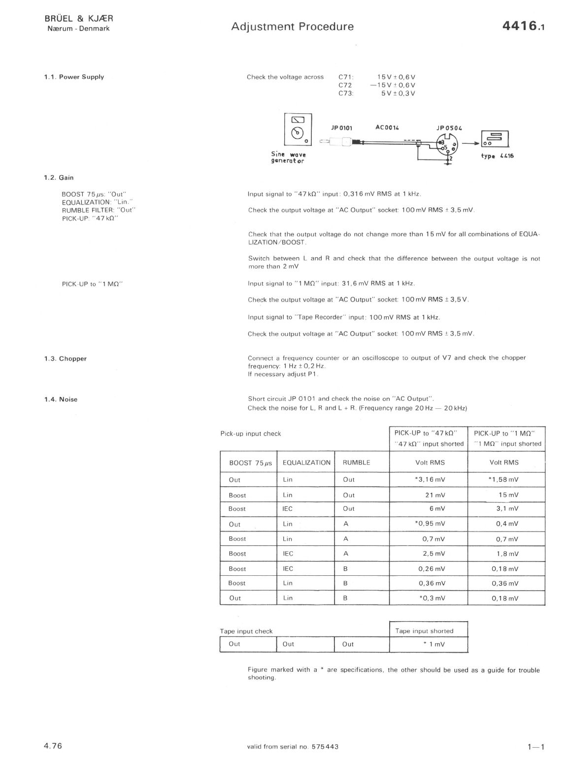
1.7 .
Rumble
Filter
BrGel &
Kjmr
-Measuri
ng
Object:
BrGel &
Kjmr
OOOOOOOODDDODOOODDOOOOOOOOOOOOOOOOOOOOOOOOOOOOOOO[
~B
Recording
No
.: Sign
.:
Date
: Potentiometer: Zero Level: 0
ABC
lin.
40
Rumble
A
30
10
o
2 Z 0
IU
OP
1143
Pot
. Range,
EQUALIZATION: "
Lin
."
CHANNEL SELECTOR:
"L
I R"
RUMBLE FILTER:
"Out
"
RUMBLE FILTER
to
"A"
RUMBLE FILTER to
"8
"
1.8.
Max.
Output
Voltage
EQUALIZATION:
"Lin"
RUMBLE FILTER:
"O
ut
"
1.9
.
Cross
talk
4.
76
EQUALIZING:
"Lin
."
CHANNEL SELECTOR: "
R"
PICK-UP"
47
kO"
PICK-UP to " 1
MO
"
o
50 dB
± 1 dB
Rumble
B
50
100
200
500
2
1000
2000
5000
'-10000
20000
50000
100000
3 mm/
sec
.
Rectifier
.:
RMS
lower
lim
.
Freq.:
Hz Writing Speed:
25
mm
/sec.
Paper Speed:
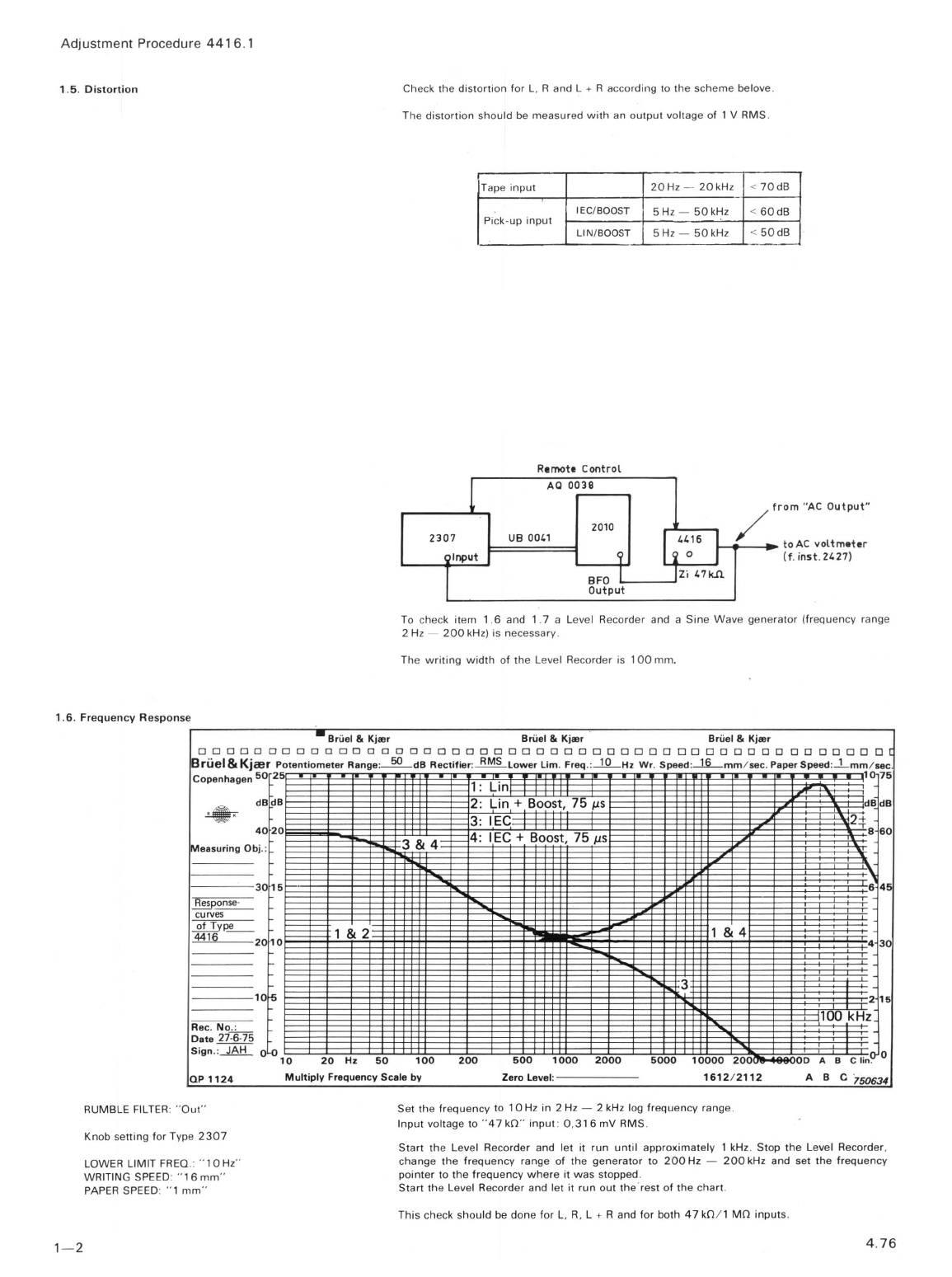
Adjust
the
input
voltage
to
exactly
1 V RMS at
315Hz
on
"AC
Output"
.
Output
voltage: 1 V RMS ±
20
mV
.
Output
voltage: 1 V RMS ±
20
mV
.
Record
the
frequency
response
for
RUMBLE A and RUMBLE B
filters
.
Connect
an osc
ill
oscope to
"AC
Output"
socket and check
that
the
output
signal is
not
dis-
tored
for
an
input
voltage
of
:
23
mV
RMS
to
"47
kO"
input
2,
3V
RMS
to " 1
MO"
input
Check max.
output
voltage for L, R, L + R and
for
both
47
kO
and 1
MO
inputs
.
Connect
the
input
signal
to
pin 3 and short
circuit
pin 5 to
gro
und
on
47
kO
input
Adjust
the
input
signal
to
3,16
V
RMS
at 1 kHz on "AC o
utput
"
Switch
C
HANNEL
SELECTOR to
"L"
and check the cross
talk
acording to
the
scheme
below
.
Inpu
t
Pi
ck-
up
Tape
fr
equency
47
kO 1
MO
1 kHz
-65
dB
-65
dB
-65dB
20
kH
z
-45d
B
-40d
B
-45
dB
50kHz
--
35
dB
-30d
B
-3
5 dB
Change
the
input
to
channe
l
"L"
and check the cross
talking.
Change
the
input
S
ignal
to " 1
MO
"
input
and check
the
cross
talk
as described
for
" 47
kO
"
input
.
Change
the
input
s
ignal
to
"Tape"
input
and
check
the
cross
talk
as described
for
" 47
kO"input
valid
from
se
rial
no
.
575443
1- 3