AXIS T92A10 Installation Guide Page 9
ENGLISH
Route the cables to the housing
The following instructions describe the installation of the housing on a bracket with an internal
cable channel.
The cable glands are not needed if the cables are routed through the wall bracket.
1. Route the cables through the holes on the underside of the housing.
2. Attach AXIS T92A10 to the wall bracket using the supplied screws.
3. Connect the network cable to the network connector on the camera.
4. If applicable, connect the I/O cables to the connectors as described in the installation guide
supplied with the camera.
5. Proceed to “Connect the power cable to the housing” on page 9.
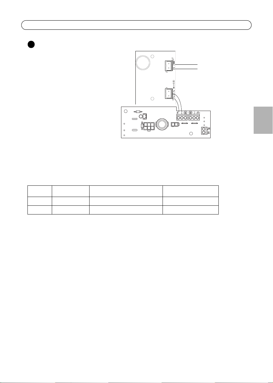
Connect the power cable to the housing
Follow the instructions below to connect the 24V AC power cable to AXIS T92A10.
Warning!
High voltage - the electrical connection should be made by an authorized electrician.
Please observe relevant national and local regulations for the installation.
1. Using the small flathead screw
driver, loosen the screws in the
Power in connector on the connec-
tor board (fig.7).
2. Insert the 24V AC wires in the
connector and tighten the screws to
secure the wires.
3. Connect screw 1 and 3 on the 110V
AC Power supply to the 24V cable (fig.8).
4. Do not apply power until the installation is
complete and all wires and cables have been
connected.
5. Proceed to “Complete the installation” on page
10.
Power in (24V AC)
24V AC
heater connector
FIG.7
screws
13
Wall
mounting
screw
FIG.8