Axeon LT-200 Manuel utilisateur
Reverse Osmosis
User’s Manual
Model
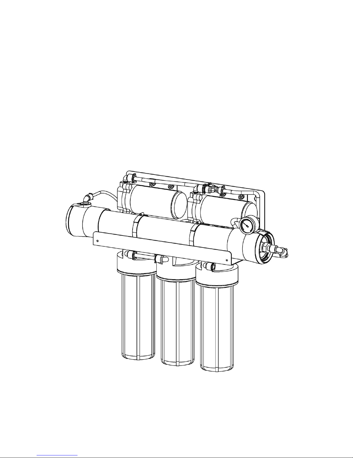
LT-200, LT-300
LT-300 Pictured

2
ENGF-110 REV. A 01/11 © 2011 AXEON Water Technologies
This Page
Left Blank

3
ENGF-110 REV. A 01/11 © 2011 AXEON Water Technologies
Table of Contents
INTRODUCTION ....................................................................................................................................... 4
SAFETY .................................................................................................................................................... 4
FEED WATER & OPERATION SPECIFICATIONS .................................................................................. 5
REJECTION, RECOVERY, & FLOW RATES ........................................................................................... 5
SYSTEM INSTALLATION AND START-UP PROCEDURES .................................................................. 6
MEMBRANE ELEMENTS ......................................................................................................................... 8
LT-200, LT-300 SYSTEM IDENTIFICATION .......................................................................................... 12
LT-200 MEMBRANE FLOW DIAGRAM .................................................................................................. 15
LT-300 MEMBRANE FLOW DIAGRAM .................................................................................................. 16
DESIGN BASIS FOR LT-200, LT 300 .................................................................................................... 17
OPERATING DO’s & DON’Ts ................................................................................................................. 18
MAINTENANCE PROCEDURES ........................................................................................................... 18
MEMBRANE REMOVAL & REPLACEMENT ......................................................................................... 20
PREPARING UNIT FOR STORAGE OR SHIPMENT ............................................................................ 22
REVERSE OSMOSIS TROUBLESHOOTING ........................................................................................ 23
TEMPERATURE CORRECTION FACTORS FOR MEMBRANE ........................................................... 25
OPERATION ........................................................................................................................................... 27
DRAWINGS............................................................................................................................................. 28
4
ENGF-110 REV. A 01/11 © 2011 AXEON Water Technologies
INTRODUCTION
Your LT-Series system is a durable piece of equipment which, with proper care, will last
for many years. This User’s Manual outlines installation, operation, maintenance, and
troubleshooting details vital to the sustained performance of your system.
The test results which are included with this User’s Manual indicate your system’s
permeate (product) and concentrate (waste) test results.
If your system is altered at the site of operation or if the feed water conditions change,
please contact your local dealer or distributor to determine the proper recovery for your
application.
NOTE: IN ORDER TO MAINTAIN THE MANUFACTURER’S WARRANTY, AN
OPERATING LOG MUST BE MAINTAINED AND COPIES WILL NEED TO BE SENT TO
YOUR LOCAL DEALER OR DISTRIBUTOR FOR REVIEW.
NOTE: PRIOR TO OPERATING OR SERVICING THE REVERSE OSMOSIS
SYSTEM, THIS USER’S MANUAL MUST BE READ AND FULLY UNDERSTOOD. KEEP
THIS AND OTHER ASSOCIATED INFORMATION FOR FUTURE REFERENCE AND
FOR NEW OPERATORS OR QUALIFIED PERSONNEL NEAR THE SYSTEM.
SAFETY
The Safety section of this User’s Manual outlines the various safety headings used
throughout this manual’s text and are enhanced and defined below:
NOTE: INDICATES STATEMENTS THAT PROVIDE FURTHER INFORMATION AND
CLARIFICATION.
CAUTION: INDICATES STATEMENTS THAT ARE USED TO IDENTIFY
CONDITIONS OR PRACTICES THAT COULD RESULT IN EQUIPMENT OR OTHER
PROPERTY DAMAGE.
WARNING: INDICATES STATEMENTS THAT ARE USED TO IDENTIFY
CONDITIONS OR PRACTICES THAT COULD RESULT IN INJURY OR LOSS OF LIFE.
FAILURE TO FOLLOW WARNINGS COULD RESULT IN SERIOUS INJURY OR EVEN
DEATH.
5
ENGF-110 REV. A 01/11 © 2011 AXEON Water Technologies
DO NOT UNDER ANY CIRCUMSTANCE; REMOVE ANY CAUTION, WARNING,
OR OTHER DESCRIPTIVE LABELS FROM THE SYSTEM.
FEED WATER & OPERATION SPECIFICATIONS
Nothing has a greater effect on a reverse osmosis system than the feed water quality.
NOTE: IT IS VERY IMPORTANT TO MEET THE MINIMUM FEED WATER
REQUIREMENTS. FAILURE TO DO SO WILL CAUSE THE MEMBRANES TO FOUL
AND VOID THE MANUFACTURER’S WARRANTY.
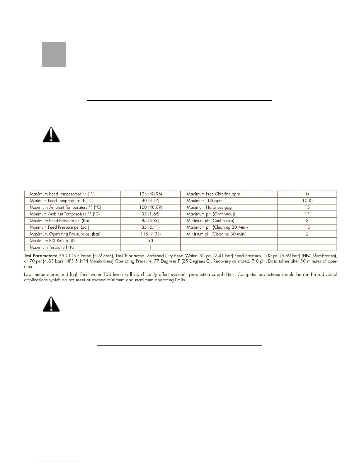
OPERATING LIMITS
NOTE: HIGHER TDS AND/OR LOWER TEMPERATURES WILL REDUCE THE
SYSTEM’S PRODUCTION.
REJECTION, RECOVERY, & FLOW RATES
LT-Series reverse osmosis systems are designed to produce permeate water at the
capacities indicated by the suffix in the system’s name under the conditions listed
above. For example, the LT-300 produces 300 gallons per day of permeate water at
the listed operating test conditions.
The amount of total dissolved solids (TDS) rejected by the membrane is expressed as a
percentage. For example, a 98.5% rejection rate means that 98.5% of total dissolved
6
ENGF-110 REV. A 01/11 © 2011 AXEON Water Technologies
solids do not pass through the membrane. To calculate the % rejection, use the
following formula:
% Rejection = [(Feed TDS – Product TDS) / Feed TDS] x 100
Example:
98.5% = [(550-8.25)/550] x 100
NOTE: ALL TDS FIGURES MUST BE EXPRESSED IN THE SAME UNITS,
TYPICALLY PARTS PER MILLION (PPM) OR MILLIGRAMS PER LITER (MG/L).
LT-Series reverse osmosis systems are designed to reject up to 98.5% NaCl, unless
computer projections have been provided or stated otherwise.
The amount of permeate water recovered for use is expressed as a percentage. To
calculate % recovery, use the following formula:
% Recovery = (Product Water Flow Rate / Feed Water Flow Rate) x 100
Example:
28% = (0.14/0.50) x 100
NOTE: ALL FLOW RATES MUST BE EXPRESSED IN THE SAME UNITS,
TYPICALLY GALLONS PER MINUTE (GPM).
SYSTEM INSTALLATION AND START-UP PROCEDURES
1. Inspect the system for any damage that could have occurred during shipment.
Although our systems have been individually inspected, complete a quick inspection
of the fittings, tubing, and other components.
2. Please provide a reasonable amount of space for installation and leave 6 inches of
space below the filter housings for ease of maintenance.
7
ENGF-110 REV. A 01/11 © 2011 AXEON Water Technologies
NOTE: THE REVERSE OSMOSIS SYSTEM SHOULD BE INSTALLED
INDOORS AND IT IS SUGGESTED THAT IT NOT BE IN DIRECT SUNLIGHT OR
EXTREME COLD.
3. Connect the 3/8” or 1/4” tube fitting to an incoming water source. The minimum
water pressure should be at least 30 psi. The system’s minimum operating pressure
is 80 PSI, but the optimum operating pressure is 100 psi.
NOTE: DO NOT OPERATE AT A PRESSURE EXCEEDING 125 PSI. The
operating pressure can be increased on the face of the booster pump by turning the
hex screw clockwise.
4. Connect the concentrate 1/4” tubing (waste) line to drain.
5. Plug the booster pump transformer into a power supply of 110 or 220 volts.
6. This system has been designed with an auto-flush restrictor. This restrictor
automatically flushes the reverse osmosis system for 30 seconds every time it starts
up and once every hour when the system is producing water.
NOTE: THE TANK PRESSURE SWITCH WILL SHUT THE SYSTEM OFF
AUTOMATICALLY, WHEN THE BLADDER TANK IS FULL.
7. The sediment filter and carbon must be serviced regularly for optimal performance.
The filters and water quality should be checked every two weeks minimum.
8. Dispose of the product water until the conductivity of the product water reaches your
desired level. Use any TDS or Conductivity meter to monitor the product water
quality. A minimum quality of 96% NaCl rejection is recommended.

8
ENGF-110 REV. A 01/11 © 2011 AXEON Water Technologies
NOTE: ANY CHLORINE EXPOSURE WILL DAMAGE THE MEMBRANE
PERMANENTLY.
9. This system has been factory wired and preset with a pressure switch at 20 - 40 psi,
which is only to be used with a pressurized bladder tank. If using an atmospheric
storage tank, a float switch will be required to turn the system ON and OFF.
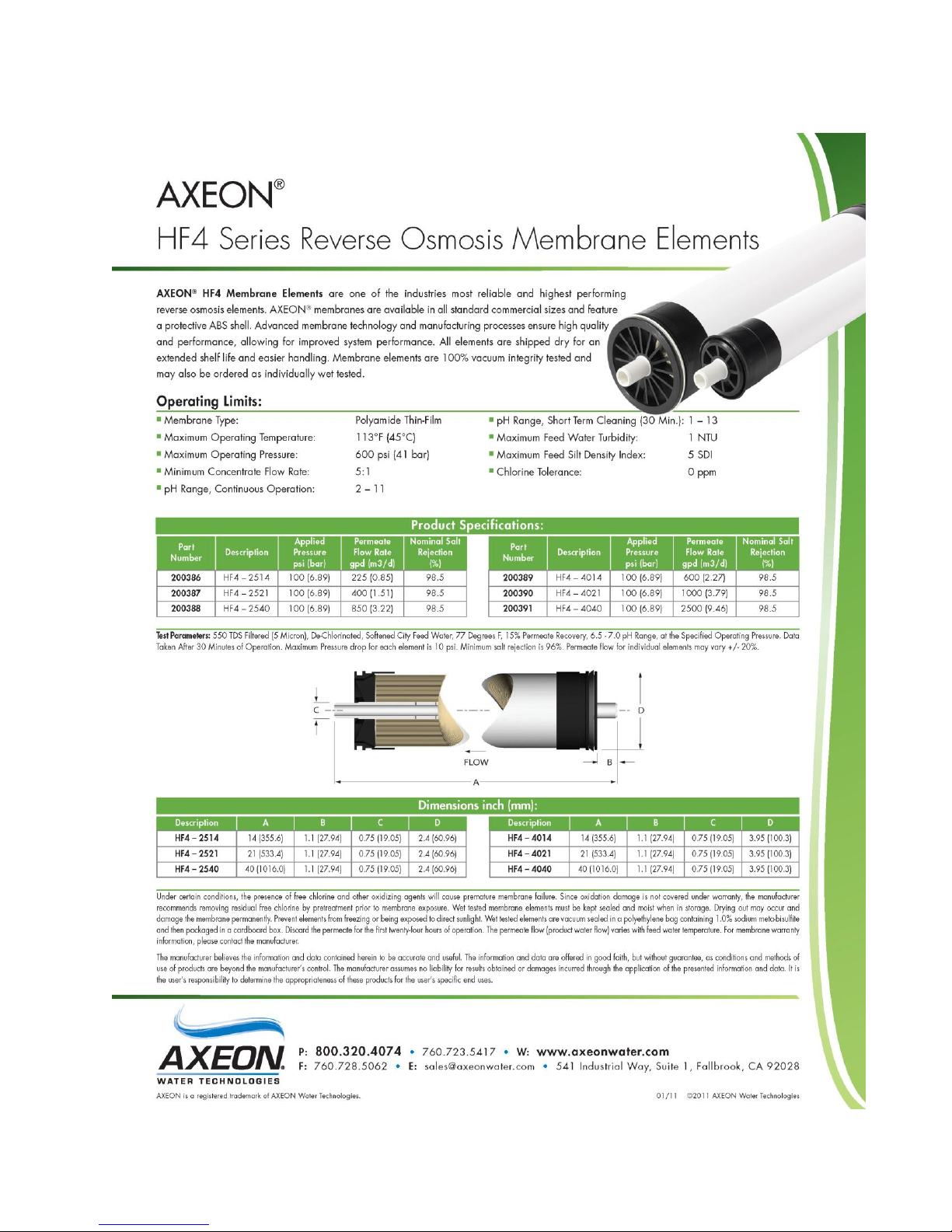
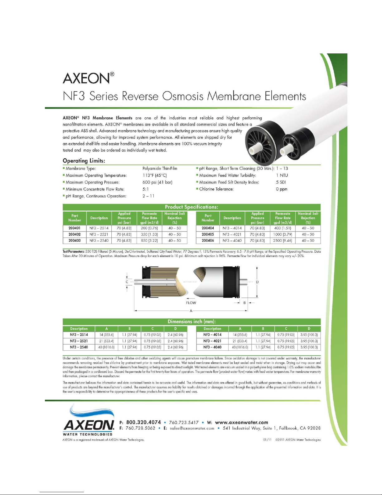
MEMBRANE ELEMENTS
LT-Series reverse osmosis systems come pre-loaded with Thin Film Composite (TFC)
HF4 High Flow Low Energy membranes, unless otherwise specified. General
membrane element performance characteristics are listed on the next page.
9
ENGF-110 REV. A 01/11 © 2011 AXEON Water Technologies
HF4-STANDARD
10
ENGF-110 REV. A 01/11 © 2011 AXEON Water Technologies
NF3-OPTIONAL
Autres manuels pour LT-200
1
Ce manuel convient aux modèles suivants
1
Table des matières
Autres manuels Axeon Système de filtration d'eau


Manuels Système de filtration d'eau populaires d'autres marques

Wisy
Wisy LineAir 100 Manuel utilisateur

Schaffner
Schaffner Ecosine FN3446 Series Manuel d'utilisation

Pentair
Pentair FLECK 4600 SXT Guide de l'utilisateur

H2O International
H2O International H20-500 Manuel utilisateur

Renkforce
Renkforce 2306241 Manuel utilisateur

Neo-Pure
Neo-Pure TL3-A502 Manuel utilisateur


