AUTOK TC818 Manuel utilisateur

TC818
TENSION CONTROLLER
INSTRUCTION MANUAL(V4.00)

Table of Contents
Note: This manual is applicable to software version 4.00 or later.
1 Introduction .......................................................................... 1
1.1 Overview .......................................................................... 1
1.2 Features ........................................................................... 1
1.3 Order code ....................................................................... 2
1.4 User interface ................................................................... 2
2 Mounting and electrical wiring .............................................. 4
2.1 Dimension ........................................................................ 4
2.2 Mounting .......................................................................... 4
2.3 Electrical connection ........................................................ 5
3 Menu operation .................................................................... 7
3.1 Overview of operation ...................................................... 7
3.2 Introduction to major screens .......................................... 8
4.2 Operation ....................................................................... 15
4.3 Taper tension control ...................................................... 23
5 Diameter Tension Control ................................................... 24
5.1 Introduction ..................................................................... 24
5.2 Roll radius monitoring ..................................................... 25
5.3 Basic operations ............................................................. 27
5.4 Constant tension control ................................................. 28
5.5 Taper tension control ...................................................... 29
5.6 Program tension control ................................................. 30
6 Additional functions ............................................................ 32
7 Serial communications ........................................................ 33
8 Appendices .......................................................................... 37
8.1 Parameters screen ......................................................... 37
8.2 Troubleshooting .............................................................. 38
8.3 Technical specifications .................................................. 39
3.3 Parameter list .................................................................. 9
4 Automatic tension control ................................................... 11
4.1 Tension measurement .................................................... 11
6.1 Language ....................................................................... 32
6.2 Parameters backup ........................................................ 32
6.3 About infos ..................................................................... 32

1.1 Overview
The TC818 tension controller is part of a closed-loop tension control system with tension sensor feedback.
The controller continuously controls the web tension to the setting tension value and display the true web
tension on an LCD screen. The screen will display the tension applied to each tension sensor separately.
The controller has a graphic LCD display
0~24V/4A output, the
controller can also outputs 0~5V, -5V~+5V, this can drive the inverter, servo motor or other power units.
The TC818 can be used in papermaking, printing, packaging, textile, print and dyeing industries, etc.
Chapter 4 covers automatic tension control and the Chapter 5 covers diameter tension control.
, Chinese and English menu selectable, the user interface is friendly
and easy to use.
The controller can drive the magnetic powder brake/clutch directly with its built-in
Powder brake
Powder brake
Proximity switch
Automatic Tension Control Radius Tension Control
ad cell
Lo
● 128x96 graphic LCD, Chinese and English ● Diameter tension control.
menu, easy to use. ● RS232/RS485 communication interface, the
● Full digital circuits, no potentiometer. controller can be used to form Distributed
● Control System(DCS) with PLC and PC.
●
● input, can be used ● Two reel exchange.
with several kinds of tension sensors: ● Acceleration and deceleration operation.
1. Micro-displacement based tension sensor ● Automatic/Manual tension control.
(signal: 200mV, power supply: 5V DC) ● Parameters protection by password, avoid
2. Strain gauge based tension sensor inadvertent modification.
(signal: 20mV, power supply: 10V DC) ●
3. 2K potentiometer in dancer control system
● Taper tension control.
High and stable measurement and easy
tension calibration. Build-in PI algorithm.
Single/Dual tension signal
Wide range input switching power
supply(92~264V AC).
1.2 Features
1 Introduction
1
Tension Controller TC818
TC818
TC818

1.4 User interface
TC818
Tension Controller
OUT
mm
%
kg/N
OUTPUT
ON /O FF
MANUAL
AUTO
COM
LOCK
ALM
OUTA OUTB
AUTO
MAN
Set Esc
AUTOK
1. LCD display22. 7-seg display
2. Lock indicator
3. Lock key
19. Output LED
18. Output ON/FF LED
17. Output ON/OFF
switch
15. , Increase key
16. , Decrease key
13. Set, Confirm
21. Content LED
14. Esc, Escape
20. LED display
selector
8. Digital knob
4. Automatic mode LED
6. Manual mode LED
7. Auto/Manual switch
5. Door open screw
9. OUTA, Reel A output indicator
10. OUTB, Reel B output indicator
11. ALM, Tension alarm indicator
12. COM, Communication indicator
1.3 Order code
Main Output Aux Output1 Aux Output2 Comms Version
2
(1) (2) (4) (5)
Code
0
RS232
RS485
None
RS232 interface, 3 wires
RS485 interface, 2 wires
Meaning
(4) Communication
Code
V1.00
V2.00
V3.00+
Radius tension controller
Automatic tension controller
Automatic and Radius tension
controller
Meaning
(5) Software Version
24V
36V
0
Code
24V/4A, drive magnetic
powder brake/clutch
36V/3A, drive magnetic
powder brake/clutch
None
Meaning
(1) Main Output
(3)
Code examples:
(1) TC818-36V/0/0/0-V3.00 designates the controller with
(2) TC818-24V/V05/V05/0-V4.00 designates the controller with 24V/4A main output and with 0~ 5V auxiliary output
1 and auxiliary output 2, drive torque motor driver or inverter, software version is V4.00.
36V/3A main output which can drive magnetic powder
brake/clutch, software version V3.00.
Code
None
0~5V DC
-5V ~ +5V DC
Meaning
0
V05
V05PN
(2) Auxiliary Output 1
0~10V DC
4~20mA DC
V10
A420
(3) Auxiliary Output 2
Tension Controller TC818
TC818 - -
/ / /

1. Set/Esc
Set: Enter the next menu screen or confirm operation.
Esc: Back to previous menu screen or “Confirm/Exit” after finishing the setting of the value.
2. AUTO/MAN switch and indicators
The automatic mode and manual mode can be switched by pressing this key.
In automatic mode, the indicator AUTO will be lit, at this time, the setting tension can be altered by
pressing the Inc/Dec key or turning the digital knob.
The flash of AUTO LED indicates that the controller is in stopping mode.
In manual mode, the indicator MAN will be lit, at this time, the output can be altered using the Inc/Dec key
or turning the digital knob.
While switching the controller from manual mode to automatic mode, the measured tension before
switching will be used as the setting tension for automatic control, this makes the smooth transition.
If the measured tension is incorrect and the error code appears, the controller will switch to manual mode
automatically, in this case, the controller can not be switched to automatic mode.
3. OUTPUT ON/OFF switch and Indicator
The output of Reel-A and Reel-B can be turned ON and OFF by pressing the 'OUTPUT ON/OFF' switch.
When the indicator is lit, output is 'ON' otherwise the output is 'OFF'.
4. LED display selector and Content LED
The type of contents displayed on the 7-seg display is changed every time the LED Display Selector is pressed.
The type of contents displayed is indicated by the Content LED provided on the left side of the 7-seg display:
kg/N: measured tension in kg or Newton
% : output
mm : radius in mm
5. LOCK key and Indicator
This key is used to lock/unlock the keypad except the LED display selector.
Lock indicator is on: keypad locked.
Lock indicator is off: keypad unlocked.
If set Function[29] to Radius control, in "Enter PWD" screen, the reel radius can be initialized to initial
radius R0. In this case, if Ctrl Mode[30] = Program Ctrl, the "Radius-Output" parameter list can be revealed
using the LOCK key, at this time, the user can alter the value of the parameters.
6. OUT: Output indicator
The brightness of this green LED indicates the magnitude of the output, the brighter LED, the greater
output. The LED will be off when the output is zero.
7. OUTA: Reel A output indicator
This LED indicates the output states of Reel A, it is lit when output of Reel A is ON.
8. OUTB: Reel B output indicator
This LED indicates the output states of Reel B, it is lit when output of Reel B is ON.
9. ALM: Tension alarm indicator
According to the setting of Alarm Mode[44] and Alarm Value[04], this red indicator ALM will be lit when
the alarm condition appears. At the same time, the relay ZT will be 'ON' to output an alarm signal. The alarm
function does not act in Run/Stop and reel exchange progress. See 4.2.9 Alarm for details.
10. COM: Communication indicator
The indicator COM flashes when the controller is in active communication with a host computer.
3
Tension Controller TC818

TC818
Tension Controller
OUT
mm
%
kg/N
OUTPUT
ON /OF F
MANUAL
AUTO
COM
LOCK
ALMOUTA OUTB
AUTO
MAN
Set Esc
AUTOK
4-M4
80+
-
0.5
232
+
-
0.5
150+
-
0.5
245
228
16.5 140
147
154
60
60
2.1 Dimensions
2.2 Mounting
256
168
TC818
Tension Controller
OUT
mm
%
kg/N
OUTPUT
ON/O FF
MANUAL
AUTO
COM
LOCK
ALMOUTA OUTB
AUTO
MAN
Set Esc
AUTOK
172.5
2~4mm
140
2 Mounting and electrical wiring
4
unit: mm
244+
-
0.5
The controller can be installed on floor, wall or panel.
Installed on floor Installed on wall Installed on panel
4-M4*12
Mounting screw
Screw holes for mounting
on floor and wall Panel mounting cut-out
Tension Controller TC818

2.3 Electrical connection
Terminal block 1: Terminal block 2:
2.3.2 Connection diagram
NB
PB
NA
PA
Reel A pulse*
Reel B pulse*
Tension sensing
roller pulse*
RS485 RS232
Power Supply
(160~240VAC)
24V
DI0
DIA
DIB
GND
MC4
MC6
MC3
MC5
MC2
MC1
MCC TRG GND
TR- RXD
TR+ TXD
ZTC
ZT
EAP
EAN
SA
Run/Stop
SN
PSL
PSN
REDL
GRL
WHL
GRR
WHR
BLKL
REDR
BLKR
Tension
Sensor
Left
power+(red)
signal+(green)
signal-(white)
power-(black)
ZT
power+(red)
signal+(green)
signal-(white)
power-(black) +
-
+
-
*NPN pulse
} }
}
}
}
2.3.1 Connection notes
5
Tension
Sensor
Right
[1] In order to avoid electrical noise to the input signal, the signal line should be away from the power line.
[2] If the AC power supply is connected to the I/O terminals or DC supply terminals, the tension controller will
be burn out.
[3] Connect the tension sensor according to the wiring diagram, pay more attention to the wiring of tension
sensor if two tension sensors are connected otherwise the measurement value will be incorrect.
[4] When one tension sensor is used, make sure to short-circuit the unused tension signal terminals.
Tension alarm output
Aux. output 1(drive Reel A power unit)
(0~5V/0~10V/4~20mA/0~20mA)
Aux. output 2(drive Reel B power unit)
(0~5V/0~10V/4~20mA/0~20mA)
Acceleration button
Deceleration button
Output ON/OFF button
Start output selector
Reel exchange
Note:
The color of the wire is optional, please
refer to the sensor's manual for
appropriate connection.
Tension Controller TC818
2K pot.
GRL
WHL
Reel A
Clutch/Brake
Reel B
Clutch/Brake
Main output A
24V/4A
Main output B
24V/4A

2.3.3 Terminals description
Terminal block 1:
Terminal block 2:
SN
1
2
3
4
5
6
7
8
10
9
11
12
13
Terminal
PSL, PSN
ZT, ZTC
PA NA,
PB, NB
MCC
MC1
MC2
MC3
MC5
MC4
MC6
+24V, GND
DI0
Specification Comments
IN
OUT
OUT
OUT
IN
IN
IN
IN
IN
IN
IN
IN
OUT
85~264V AC, 50/60 Hz
Relay, 3A/250VAC, NO
I/O
Controller Power supply
Tension alarm output
drive Reel A magnetic powder clutch/brake
drive Reel B magnetic powder clutch/brake
External switch/button input common terminal
Run/Stop
Reel exchange
Acceleration button
Deceleration button
Start output selection
External OUTPUT ON/OFF button
Power supply for proximity switch/Encoder
Main roller proximity switch pulse inputMax frequency 15kHz
24V/4A or 36V/3A
24V/4A or 36V/3A
SN
1
2
3
4
5
6
7
8
9
10
11
12
13
Terminal
DIA
DIB
GRL
WHL
REDL
BLKL
GRR
WHR
REDR
BLKR
SA SN,
EAP, EAN
TR+,TR-,TRG
Specification Comments
IN
IN
IN
IN
OUT
OUT
IN
IN
OUT
OUT
OUT
OUT
OUT
Max frequency 15kHz
I/O
Reel A proximity switch pulse input
Reel B proximity switch pulse input
Left tension sensor signal+
Left tension sensor signal-
Left tension sensor power supply+
Left tension sensor power supply-
Right tension sensor signal+
Right tension sensor signal-
Right tension sensor power supply+
Right tension sensor power supply-
Sync. output, 0~5V(drive Reel A power unit)
Output 2, 0~5V(drive Reel B power unit)
RS232/RS485 communication interface
RS232, RS485
0~200mV or
0~20mV or
2K pot.
14 +5V,0V OUT Auxiliary power supply
5V or
10V
0~200mV or
0~20mV
5V or
10V
0~20mA or 0~5V
0~20mA or 0~5V
6
24V DC
Left
Right
Tension Controller TC818
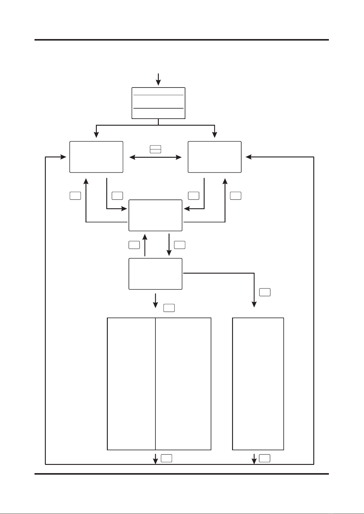
3.1 Overview of operation
AUTO
MAN
Set
Set
Esc
Set Set
Esc Esc
Password: 808
Password: 818
Set
Operation parameters menu
Complete setup menu
Esc Esc
Auto Monitor
PV.: 24.9kg
SV.: 25.0kg
Out: 39.5%
Man Monitor
PV.: 24.9kg
SV.: 25.0kg
Out: 39.5%
Tension
Left: 24.9kg
Right: 25.0kg
Total: 49.9kg
Enter PWD
Password: 808
Set:OK. Esc:Exit
3 Menu operation
Power ON
TC818张力控制器
软 件 版 本: ver2.20
Select the menu item
with the knob, press
Set key to enter
parameter setting
screen
01.Init Radius
02.Thickness
03.Start Freq
04.Alarm Value
05.Prop. Band
06.Inte. Time
07.Dead Band
08.StartOutput
09.Start Gain
10.Start Time
11.Stop Gain
12.Stop Time
13.Exch. Out
14.Exch. Time
15.Aux. Time
16.Inc Coeff.
17.Dec Coeff.
中文
27.Addr
28.Baud Rate
29.Function
30.Ctrl Mode
31.Taper t1
32.Count Mode
33.Max Radius
34.Min Radius
35.Radius R0
36.Pulse N1
37.Pulse N2
38.Calc Cycle
39.Torque
40.Wind Mode
41.Action Mode
42.Sync Mode
43.OUT2 Mode
18.Max SetVal 44.Alarm Mode
19.Min SetVal 45.OUTA SIGNAL
20.Max Output 46.OUTB SIGNAL
21.Min Output 47.In Filter
22.Left Offset 48.Zero cali.
23.RightOffset 49.Span Cali.
24.Sensor 50.English
25.Unit 51.Backup
26.Signal 52.About
▲
01.Init Radius
02.Thickness
03.Start Freq
04.Alarm Value
05.Prop. Band
06.Inte. Time
07.Dead Band
08.StartOutput
09.Start Gain
10.Start Time
11.Stop Gain
12.Stop Time
13.Exch. Out
14.Exch. Time
15.Aux. Time
16.Inc Coeff.
17.Dec Coeff.
▲
7
After powered on, the controller
will return to the state before
shutting down.
Tension Controller TC818

3.2 Introduction to major screens
(1) Automatic tension control: constant tension
(2) Automatic tension control: taper tension
(4) Tension monitor
(5) Password
(6) Parameters menu
Select the parameter using the Inc/Dec key or the knob
Press Set to enter the parameter screen
Press Esc to Exit
Change the password by pressing the Inc/Dec key or turning the digital knob
[1] Password=808, enter the operation parameter menu
[2] Password=818, enter the complete setup parameter menu
Alter the setting tension using the Inc/Dec key or digital knob
Measured tension
Output
Measured tension of the left sensor
Measured tension of the right sensor
Total tension = Left + Right
Auto Monitor
PV.: 24.9kg
SV.: 25.0kg
Out: 39.5 %
Tension
Left: 24.9kg
Right: 25.0kg
Sum: 49.9kg
Enter PWD
Password: 808
Set:OK. Esc:Exit
01.Init Radius
02.Thickness
03.Start Freq
04.Alarm Value
▲
Alter setting tension using the Inc/Dec key or knob
Target tension:
This value is calculated with the setting tension, radius and taper coefficient t1.
Output
Taper Tension
SP.: 18.0kg
SV.: 25.0kg
OUT: 28.5%
Note: The measured tension can be viewed in the LED display when the kg/N indicator is lit.
Note: In order to void inadvertent modification, change the password other than 808 after configuration.
(3) Manual tension control
Alter the output using the Inc/Dec key or knob
Measured tension
Man Monitor
PV.: 24.9kg
SV.: 25.0kg
Out: 39.5 %
8
Tension Controller TC818
Table des matières
Autres manuels AUTOK Contrôleurs


