Audiovox MS-306 Manuel utilisateur

ROwner’s Manual
AM/FM STEREO RADIO
WITH AUTO REVERSE CASSETTE PLAYER
Designed Specifically for
the Marine Environment
MS-306
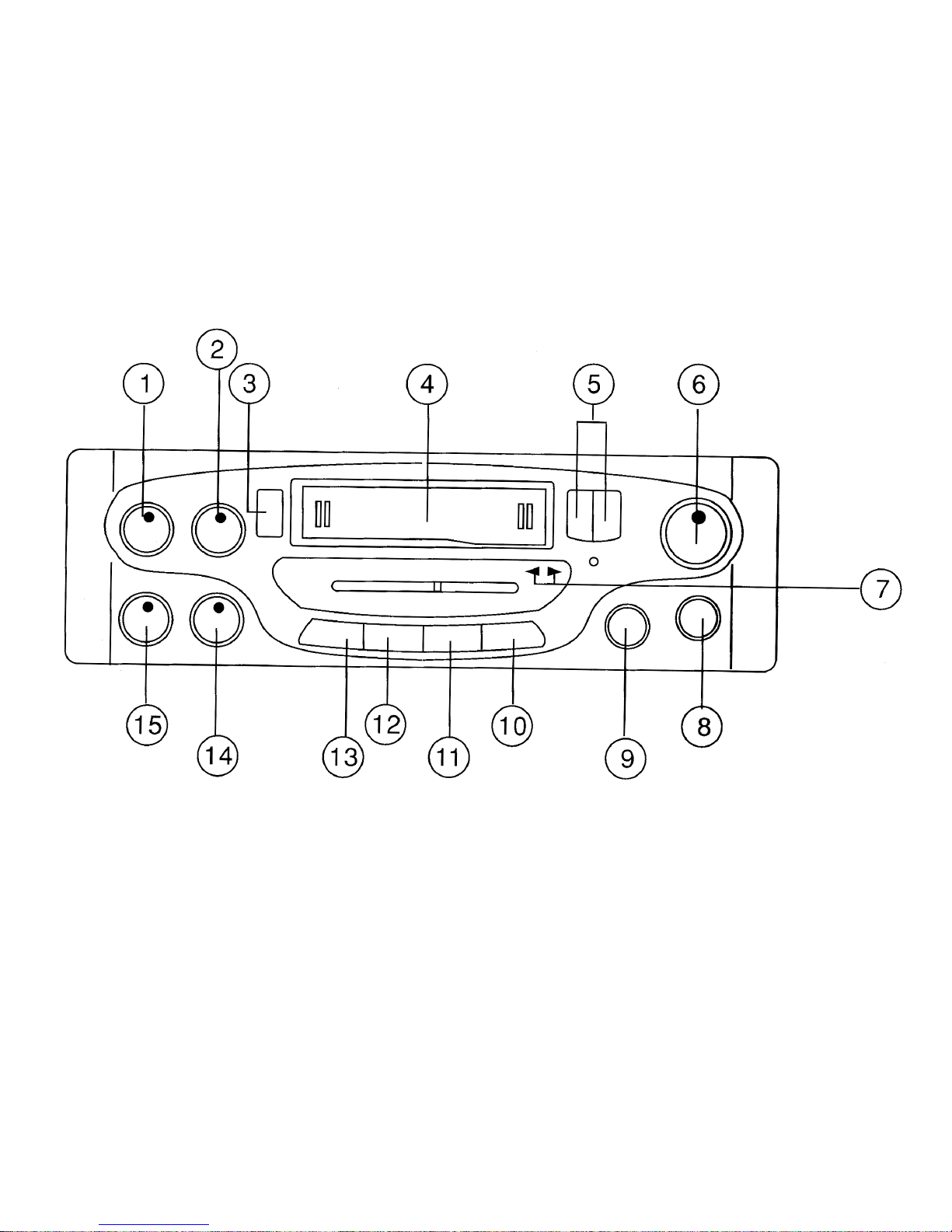

1. POWER ON/OFF VOLUME
Rotate knob clockwise past detent to turn radio “ON”. Further rotation increases the volume.
Rotate knob counter-clockwise past detent to turn the radio “OFF”. Counter-clockwise rotation
decreases the volume.
2. FADER CONTROL
Clockwise rotation shifts the signal to the Left/Right front speakers. Counter-clockwise rotation
shifts the signal to the Left/Right rear speakers.
3. EJECT BUTTON
Press this button to stop the tape playback and resume radio operation; at the same time
cassette tape will be ejected from the cassette slot.
4. CASSETTE SLOT
Hold the cassette with the exposed tape edge to the right and insert into the cassette slot.
Depress fully until the tape is engaged. Tape will enter Play immediately.
5. FAST FORWARD/REWIND BUTTONS
These buttons cause the tape to move rapidly in the direction indicated by the tape direction
arrows. For example, if the “>>” button is pushed when the tape is playing from left to right, the
tape will fast forward. If pushed when the tape is moving from right to left, the tape will rewind.
The direction of tape movement is shown by the PROGRAM INDICATORS (7). To stop fast tape
movement, lightly push the opposite button. If the tape is allowed to fast forward or rewind all the
way to the end, play will automatically begin from that point.
6. TUNING KNOB
Rotate the tuning knob clockwise or counter-clockwise to tune in the station of your choice.
Adjust the knob until the station is received with the best possible reception.

7. PROGRAM INDICATORS
Indicates tape direction for reference to the fast forward/reverse buttons. Further indicates the
direction (side) of the tape currently playing. To reverse the tape direction and play the other
side of the cassette, lightly press both << and >> (5) buttons at the same time. The change of
direction will be shown by the indicators.
8. MUTE SWITCH
Press the switch “IN” to activate the audio mute circuit. Press the switch again to return to the
previous output level.
9. BALANCE CONTROL
Clockwise rotation shifts balance to the right speakers and counter-clockwise shifts balance to
the left speakers. Detent position in the center balances the left and right speakers.
10. LO/DX SWITCH
Press the switch to the “IN” position, local reception is gained and by pressing once more to
“OUT” position, the antenna will be able to work on distant reception.
11. MONO/STEREO SWITCH
The Mono position of the switch is used when the FM stereo signal has become weak and begins
to switch the stereo light ON and OFF. For normal operation set the switch in the “IN” position for
FM stereo.
12. LOUDNESS SWITCH
This control compensates for the loss of high and low frequencies when the volume control is
adjusted to a low level.
13. AM/FM BAND SELECTOR
Press this button to the “IN” position for FM band. Press and release it to the “OUT” position for
the AM band.
14. BASS CONTROL
According to individual taste, Bass Sound can be boosted or cut by tuning this knob clockwise or
counter-clockwise respectively.
15. TREBLE CONTROL
According to individual taste, Treble Sound can be boosted or cut by tuning this knob clockwise
or counter-clockwise respectively.
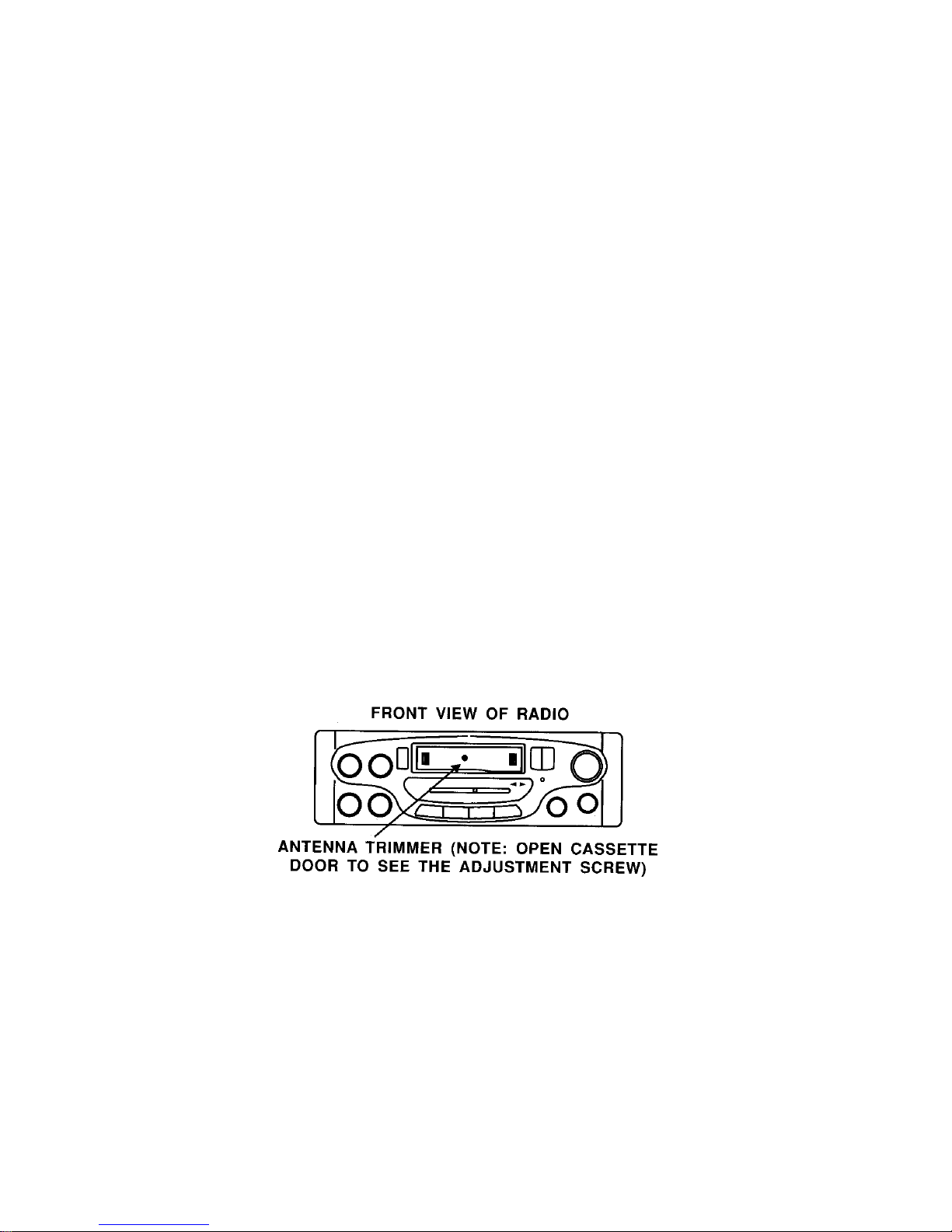
AM ANTENNA TRIMMER ADJUSTMENT
The antenna trimmer can be accessed through the small hole inside the cassette door (See
diagram below) Tune radio to a weak station between 1200 and 1400 KHz AM. (If you cannot
find a weak station in this range, tune to any strong station, and adjust tuning slightly off station).
Adjust trimmer for maximum volume.

CARE & MAINTENANCE
Cassette
Always check that the tape is tightly wound inside the take-up
spool on the cassette. If the tape is loose, wind it with a six-sided
pencil. Never use C-120 (120 minute) cassettes in this player.
Never use cassette player when the vehicle temperature is near
or below freezing.
Cleaning of Tape Head & Capstan
Since tapes contain oxides, you will find a black residue builds up
on the head and drive capstan (inside cassette door). These
residues should be cleaned after 50-100 hours of accumulated
tape operation. You can use cassette cleaning cartridges
available where ever stereos are sold.
DE-MAGNITIZING
The movement of the magnetic tape across the tape head and
metal parts causes a magnetic field to develop. We recommend
you have the tape player demagnetized at least twice annually.
You can purchase an inexpensive tape head demagnetizing tool
to do this yourself.
SPECIFICATIONS
Size: 7” (W) x 2” (H) x 6 5/8” (D)
178mm x 50mm x 168mm
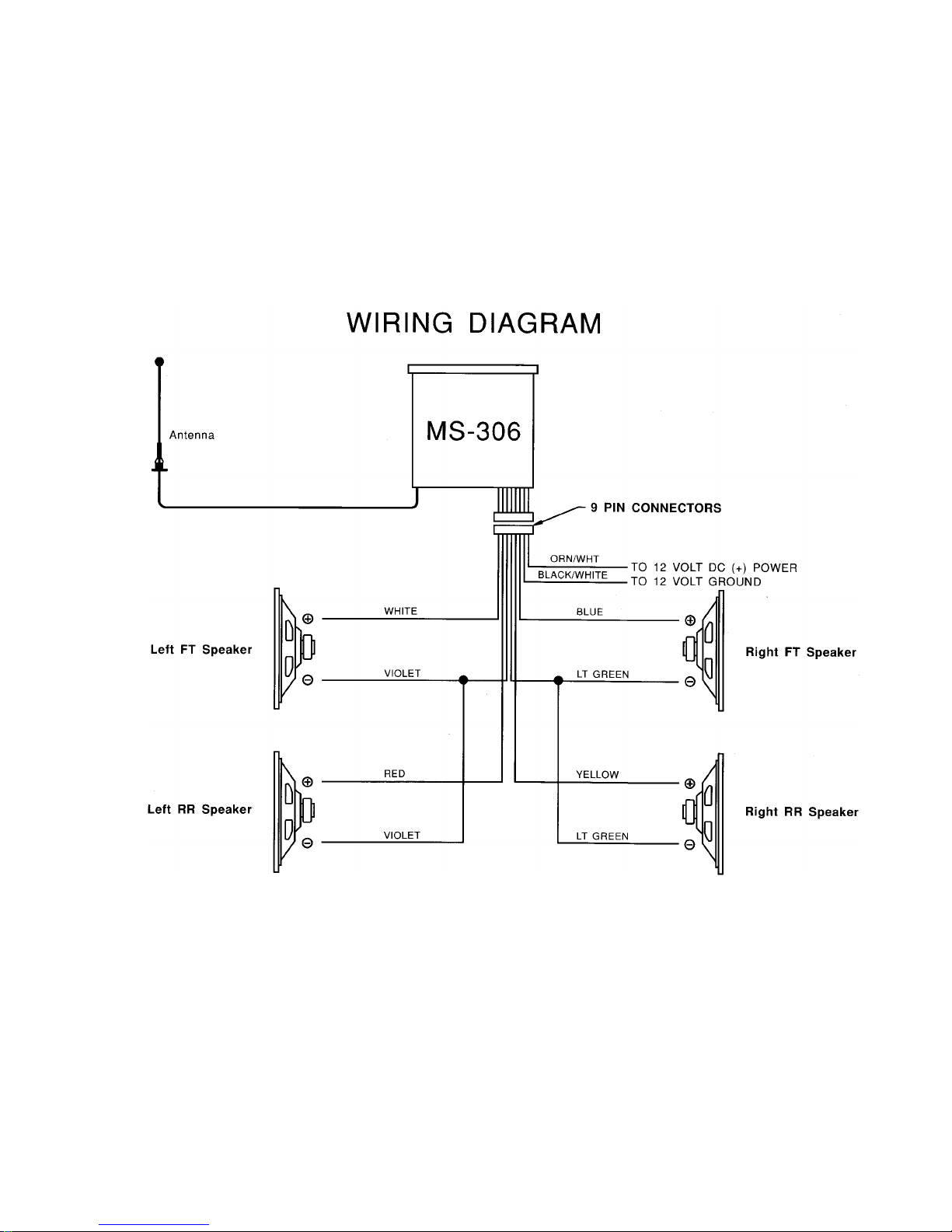
Operating Voltage: 12V DC, Negative ground
Output Power: 50 Watts max. Stereo power
Output Wiring: Floating ground type designed
for 4 speaker use. May also be
used with 2 speakers.
Output Impedance: Compatible with 4 or 8 Ω
Speakers
Tuning range: (AM) 530 – 1710 KHz
(FM) 88 – 108 MHz
Sensitivity: (AM) less than 25uV
(FM) less than 5uV
FM Stereo Separation: More than 23 dB
Frequency Response: 50 –10000 Hz
Wow & Flutter: Less than 0.3%

AM/FM RADIOS
Symptom Cause Possible Solution
No Power No 12VDC Check circuit fuse at source
Check in-line fuse on power lead
(wall mount units are located in
rear cabinet)
Power lead disconnected
Ground connection
No 12VDC to memory lead
(electronically tuned units only) Circuit fuse at source
In-line memory lead fuse
Speaker Output shorted Check continuity of speaker
leads to ground
Power indicated; No audio
output
Speaker out cross channeled Check for proper speaker wiring.
Note: Radios have a sticker on
them explaining wiring color
code.

Radio Balance Check radio function
Speaker Disconnected Check speaker connection at
radio and/or speaker
Only one channel (right or left
side)
Speaker lead shorted or
grounded Check speaker wiring continuity
to ground w/tester or meter
Popping in one or both channels Speaker wiring shorted or
positive lead grounded
Speaker terminals grounded or
shorted
Leads from speaker cone to
terminal touching metal basket
or speaker
Antenna disconnected Connect antenna
Antenna mast grounded or
shorted Check antenna or substitute with
antenna known to be good
Antenna center lead broken Check antenna or substitute with
antenna known to be good
No AM Reception
Note: Antenna leads can be tested with continuity or multi-tester.
Some may have electronic component (capacitor) built-in which will
not allow it to be tested.

Audiovox Specialized Applications, LLC
T E C H N I C A L B U L L E T I N
AM/FM RECEPTION
Many vans and RV’s have more than one
AM/FM radio. The best way to insure good reception
is to supply a separate antenna for each radio. Other
options available to supply adequate AM/FM reception
to these radios are listed below, along with some
general information in regards to radio reception.
“Y” ADAPTERS
The “Y” adapters used to connect one antenna
to two radios will only provide AM reception to one of
the radios and will compromise both AM and FM
reception.
AMPLIFIED AM/FM ANTENNA
A popular second antenna that can be used is
our AB-100 amplified AM/FM antenna. It is small
and has a retractable mast that can be mounted
vertically or horizontally. This antenna provides
good FM reception, but the AM reception will be
compromised to some degree because of the length
of the mast.
MAST LENGTH
AM/FM antennas compromise AM reception
by design. The optimum mast length for FM is
approximately 30 inches which is standard for most
automotive antennas. The optimum mast length for
AM reception is over 100 inches which is not
practical for mobile applications.
Table des matières
Autres manuels Audiovox Audio marin


Manuels Audio marin populaires d'autres marques


Nady Audio
Nady Audio M-Cab MC-15 Manuel d'instructions

Fusion
Fusion MS-RA70 Manuel utilisateur

Garmin
Garmin Fusion APOLLO RV-RA770 Manuel utilisateur

Boss Audio Systems
Boss Audio Systems ATV25B Manuel utilisateur

Polk Mono
Polk Mono UM1 Manuel utilisateur

Garmin
Garmin Fusion Apollo MS-RA670 Manuel utilisateur