ATO DMKEB Series Manuel utilisateur

DMKEB Brushless Motor
Controller User’s Manual
Devices Supported
DMKEB48200X DMKEB48201X
DMKEB48300X DMKEB48301X
DMKEB48400X DMKEB48401X
DMKEB48600 DMKEB48601
DMKEB72300X DMKEB72301X
DMKEB72450X DMKEB72451X
DMKEB72600X DMKEB72601X
DMKEB72800X DMKEB72801X
DMKEB72100 DMKEB72101
DMKEB72120E DMKEB72121E
DMKEB84600X DMKEB84601X
DMKEB84800X DMKEB84801X
DMKEB84120E DMKEB84121E
Chapter 1 Introduction ....................................................................................................... 1
1.1 Overview................................................................................................................. 1
Chapter 2 Main Features and Specifications................................................................. 1
2.1 General functions.................................................................................................. 1
2.2 Features.................................................................................................................. 3
2.3 Specifications......................................................................................................... 4
2.4 Models .................................................................................................................... 4
Chapter 3 Wiring and Installation..................................................................................... 5
3.1 Mounting the Controller........................................................................................ 5
3.2 Connections ........................................................................................................... 6
3.2.1 Front Panel of DMKEB Motor Controller: .................................................................... 6
3.2.2 Standard Wiring of DMKEB Motor Controller ............................................................. 9
3.2.3 Communication Port ...................................................................................................... 10
3.3 Installation Check List .........................................................................................10
Chapter 4 Maintenance....................................................................................................11
4.1 Cleaning................................................................................................................ 11
4.2 Configuration ....................................................................................................... 11
Table 1: LED CODES....................................................................................................... 12
Contents
DMKEB Ebike Brushless DC Motor Controller User’s Manual

Chapter 1 Introduction
1.1 Overview
This manual introduces the ebike brushless DC motor controllers‟ features, their
installation and their maintenance. Read the manual carefully and thoroughly before using the
controller. If you have any questions, please contact the support center of Controls.
‟s programmable DMKEB motor controllers provide efficient, smooth and quiet controls for
electric bicycles, electric motorcycles, scooters, etc. It outputs high taking off current, and
strictly limit battery current. It can work with relative small battery, but provide good
acceleration and hill climbing. It uses high power MOSFET‟s and, PWM to achieve efficiencies
of up to 99%.
In most cases, Powerful microprocessor brings in comprehensive and precise control to
the controllers. It also allows users to adjust parameters, conduct tests, and
obtain diagnostic information quickly and easily.
DMKEB Ebike Brushless DC Motor Controller User’s Manual
Chapter 2 Main Features and Specifications
2.1 General functions
(1) Extended fault detection and protection. The LED flashing pattern indicates the fault sources.
(2) Monitoring battery voltage. It will stop driving if the battery voltage is too high and it will
progressively cut back motor drive power as battery voltage drops until it cuts out altogether
at the preset “Low Battery Voltage” setting.
(3) Built-in current loop and over current protection.
(4) Configurable motor temperature protection range.
(5) Current cutback at low temperature and high temperature to protect battery and controller.
The current begins to ramp down at 90 ℃ case temperature, shutting down at 100 ℃.
(6) The controller keeps monitoring battery recharging voltage during regenerative braking,
progressively cutting back current as battery voltage rises then cutting off regen altogether
when voltage goes too high.
(7) Maximum reverse speed is configurable to half of max forward speed.
(8) Configurable and programmable with a host computer though RS232 or USB. Provide free
GUI which can run on Windows XP/2000, Windows 7 and Vista(recommend using standard
USB to RS232 Converter).
(9) Provision of a +5 volt output to supply various kinds of sensors, including Hall effect type.
(10) 3 switch inputs which are activated by connection to Ground. Default to throttle switch, brake
switch and reversing switch.
1

(12) Configurable boost switch. Enables the maximum output power achievable if the switch is
turned on.
(13) Configurable economy switch. Limits the maximum current to half if the switch is turned
On.Boost and Economy used the same pin as J2-6(brake-AN).Needless to say,you may not
use J2-6(brake-AN) as brake analog regen mode if you want to use Boost or Economy
function.Boost or Economy can’t be enabled at the same time in the user program.
(14) Maximum reverse power is configurable to half power.
(15) Enhanced regen brake function. A novel ABS technique provides powerful and smooth
regen.
(16) Configurable 12V brake signal input, instead of motor temperature sensor.
(17) Optional joystick throttle. A bi-symmetrical 0-5V signal for both forwarding and reversing. If
software version is 0406 or above,joystick can can be enabled or disabled in the user
program now.
(18) Configurable motor over-temperature detection and protection with the recommended
thermistor KTY84-130 or KTY83-122.
(19) 3 hall position sensor inputs. Open collector, pull up provided.
(20) Optional supply voltage 8V-30V.
(21)Cruise control.Can not be activated in reversing direction.If software version is 0406
or above,cruise control can be enabled or disabled in the user program now.If you hold
throttle at certain position about 3-4 seconds,the controller will get into Cruise control.
DMKEB Ebike Brushless DC Motor Controller User’s Manual
(22) CAN Bus is not supported in DMKEB controller.
Regeneration has braking effect but does not replace the function of a mechanical
brake. A mechanical brake is required to stop your vehicle. Regen IS NOT a safety
feature! Controller may stop regen, without warning, to protect itself or the battery(it
won’t protect you!).
(11) 3 analog inputs 0-5V inputs that default to throttle input, brake input and motor temperature
input.
Caution :
2

2.2 Features
• Specially designed for electric bicycle and scooter.
• Intelligence with powerful microprocessor.
• Synchronous rectification, ultra low drop, fast PWM to achieve very high efficiency.
• Electronic reversing.
• Voltage monitoring on 3 motor phases, bus, and power supply.
• Voltage monitoring on voltage source 12V and 5V.
• Current sense on all 3 motor phases.
• Current control loop.
• Hardware over current protection.
• Hardware over voltage protection.
• Support torque mode, speed mode, and balanced mode operation.
• Configurable limit for motor current and battery current.
• Battery current limiting available, doesn’t affect taking off performance.
• More startup current ,can get more startup speed.
• Low EMC.
• LED fault code.
• Battery protection: current cutback, warning and shutdown at configurable high and low battery
voltage.
• Rugged aluminum housing for maximum heat dissipation and harsh environment.
• Rugged high current terminals, and rugged aviation connectors for small signal.
• Thermal protection: current cut back, warning and shutdown at high temperature.
• Configurable 60 degree or 120 degree hall position sensors.
• Support motors with any number of poles.
• Up to 40,000 electric RPM standard. Optional high speed 70,000 ERPM, and ultra high speed
100,000 ERPM. (Electric RPM = mechanical RPM * motor pole pairs).
DMKEB Ebike Brushless DC Motor Controller User’s Manual
• Brake switch is used to start regen.
• 0-5V brake signal is used to command regen current.
• Support three modes of regenerative braking: brake switch regen, release throttle regen, 0-5V
analog signal variable regen.
•Configurable high pedal protection: the controller will not work if high throttle is detected at
power on.
•Current multiplication: Take less current from battery, output more current to motor.
•Easy installation: 3-wire potentiometer will work.
•Standard PC/Laptop computer is used to do programming. No special tools needed.
•User program provided. Easy to use. No cost to customers.
3

DMKEB Ebike Brushless DC Motor Controller User’s Manual
2.3 Specifications
• Frequency of Operation: 16.6kHz.
• Standby Battery Current: < 0.5mA.
• 5V Sensor Supply Current: 40mA.
• Controller supply voltage range, PWR, 18V to 90V.
• Supply Current, PWR, 150mA.
• Configurable battery voltage range, B+. Max operating range: 18V to 1.25*Nominal.
• Standard Throttle Input: 0-5 Volts(3-wire resistive pot), 1-4 Volts(hall active throttle).
• Analog Brake and Throttle Input: 0-5 Volts. Producing 0-5V signal with 3-wire pot.
• Full Power Operating Temperature Range: 0℃ to 50℃(controller case temperature).
• Operating Temperature Range: -30℃ to 90℃, 100℃shutdown(controller case temperature).
• Peak Phase Current, 10 seconds: 150A-550A, depending on the model.
• Continuous Phase Current Limit: 60A-200A, depending on the model.
• Maximum Battery Current: Configurable
2.4 Models
The naming regulations of the DMKEB motor controller model:
4
Chapter 3 Wiring and Installation
3.1 Mounting the Controller
The controller can be oriented in any position which should be as clean and dry as possible,
if necessary, shielded with a cover to protect it from water and contaminants.
To ensure full rated output power, the controller should be fastened to a clean, flat metal
surface with four screws. Applying silicon grease or some other thermal conductive material to
contact surface will enhance thermal performance.
Proper heat sinking and airflow are vital to achieve the full power capability of the controller.
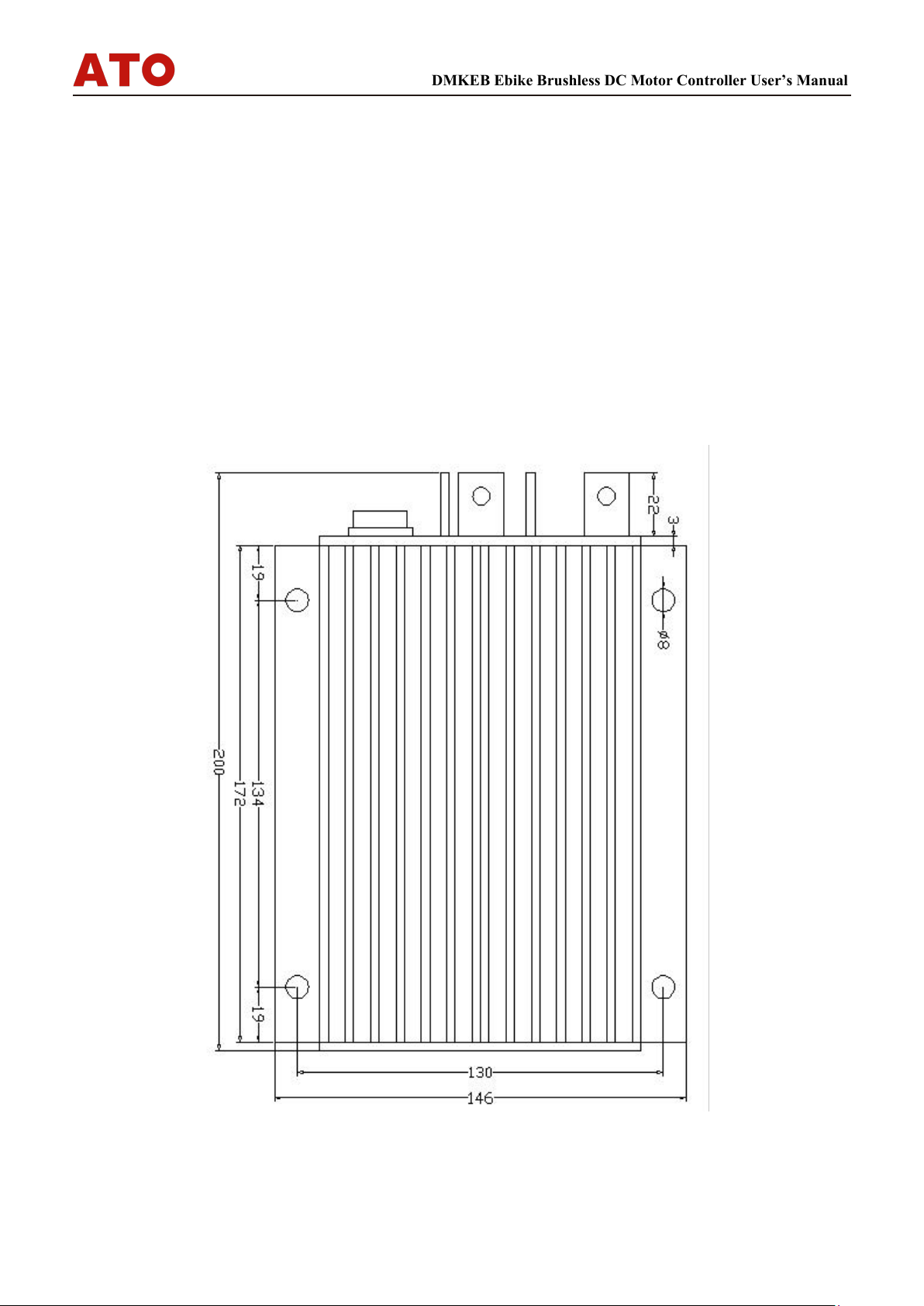
The case outline and mounting holes’ dimensions are shown in Figure 1 and 2.
Height: 62 millimeters
Figure 1: DMKEB/ DMKEB-X mounting holes’ dimensions (dimensions in millimeters)
DMKEB Ebike Brushless DC Motor Controller User’s Manual
5

Height: 62 millimeters
Figure 2: DMKEB-E mounting holes’ dimensions (dimensions in millimeters)
3.2 Connections
3.2.1 Front Panel of DMKEB Motor Controller:
Five metal bars and a 14pin rugged connector are provided for connecting to the battery,
motor and control signals in the front of the controller shown as Figure 3.
DMKEB Ebike Brushless DC Motor Controller User’s Manual
6

Figure 3: Front panel of DMKEB motor controller
B+: battery positive
B-: battery negative
A: Output U/1/A phase
B: Output V/2/B phase
C: Output W/3/C phase
Figure 4: The connecting diagram of J2
J2 Pin Definition
1. PWR: Controller power supply
2. RTN: Signal return, or power supply ground
3. RTN: Signal return
4. 12V high-level brake and motor temperature
input
5. Throttle analog input, 0-5V
6. Brake analog input, 0-5V
7. 5V: 5V supply output, <40mA 8. Micro_SW:
Throttle switch input.
9. Reversing switch input
10. Brake switch input
11. Hall phase C 12.Hall phase B
13. Hall phase A
14. RTN: Signal return
DMKEB Ebike Brushless DC Motor Controller User’s Manual
7

Caution:
•Do not apply power until you are certain the controller wiring is correct and has been
double checked. Wiring faults will damage the controller.
•Ensure that the B- wiring is securely and properly connected before applying power.
•The preferred connection of the system contactor or circuit breaker is in series with the
B+ line.
•All contactors or circuit breakers in the B+ line must have precharge resistors across
their contacts. Lack of even one of these precharge resistors may severely damage the
controller at switch-on.
Notes:
1. All RTN pins are internally connected. RTN is internally connected to B-.
2. Switch to ground is active. Open switch is inactive
DMKEB Ebike Brushless DC Motor Controller User’s Manual
8
Ce manuel convient aux modèles suivants
25
Table des matières
Autres manuels ATO Contrôleurs


