Atlas Copco Stacklight ESL-04 Manuel utilisateur
Stacklight ESL-04
Printed Matter No. 9836 2642 01
Publication Date 2019-11-22
Valid for Version No. 6 User Guide
WARNING
Read all safety warnings and instructions
Failure to follow the safety warnings and instructions may result in
electric shock, fire and/or serious injury.
Save all warnings and instructions for future reference
EN Stacklight ESL-04
2© Atlas Copco Industrial Technique AB - 9836 2642 01
Introduction
Stacklight ESL-04
Stacklight ESL-04 is a flexible light and switch device designed to interface with controllers equipped with
the following types of I/O bus connectors:
■I/O Bus connectors
■MACS I/O connectors
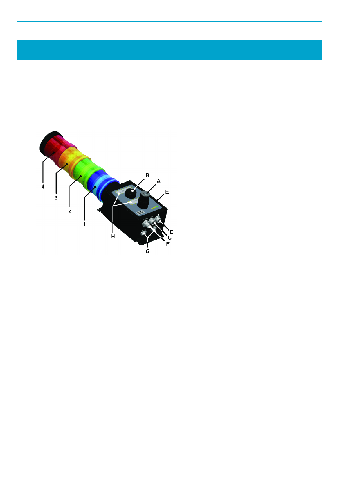
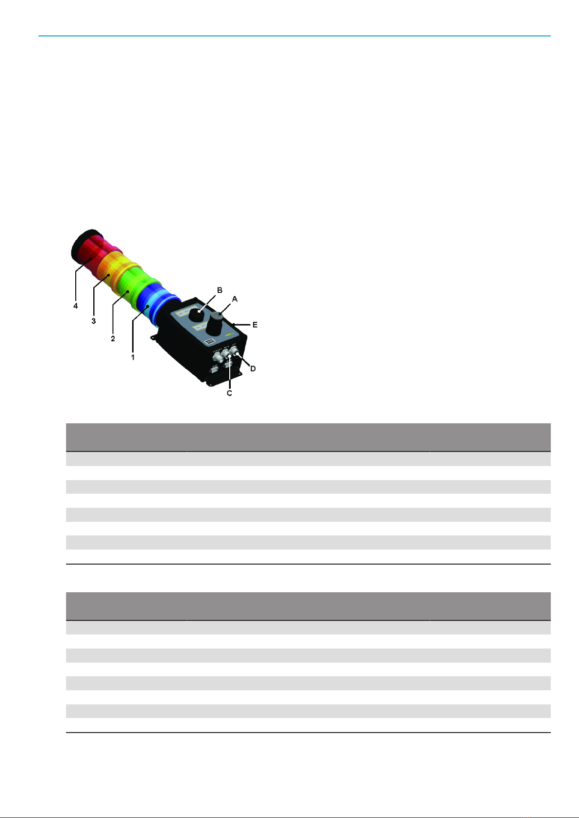
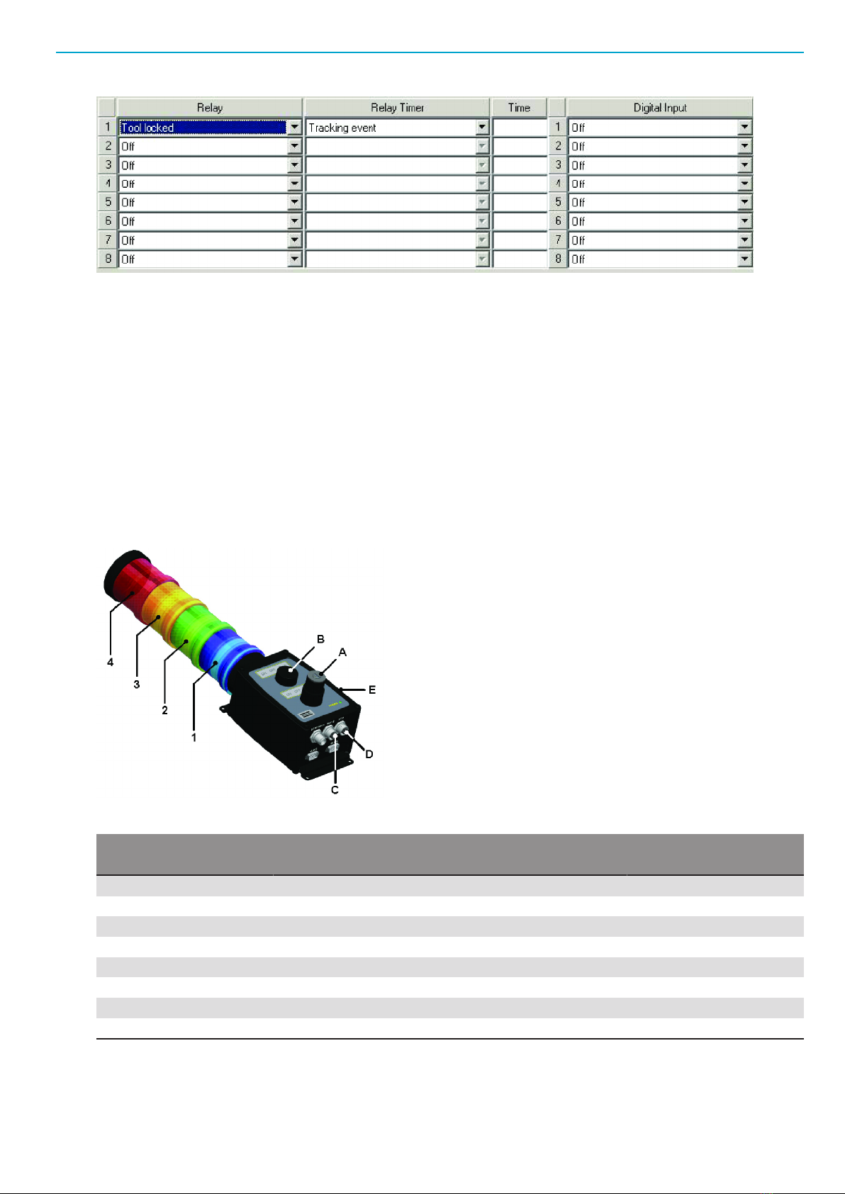
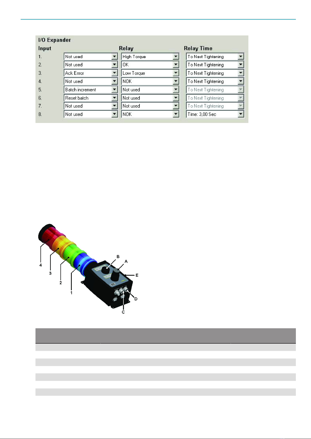
A) Key switch
B) Button switch
C) External output connector
D) External input connector
E) Buzzer
F) External power connector
G) I/O bus connectors
H) Text slip fields
1. Stack lamp
2. Stack lamp
3. Stack lamp
4. Stack lamp
The standard version of Stacklight ESL-04 offered for sale has:
■4 configurable lights
■1 configurable push button
■1 configurable key switch
■1 configurable buzzer
■24 V DC external input
■External outputs (output 1 and 2)
■External inputs (input 1 and 2)
■2 I/O bus connections
Stacklight ESL-04 can be customized as follows:
■A stack of four lights. One optional light can be added to this stack. You can also customize the order
and the color of lights.
■Two positions, A and B, which can be customized with indicator lamps or switches.
■A buzzer placed on the side of the box that has a fixed frequency of 3000 Hz. The buzzer can be con-
figured to activate on any tightening controller signal.
■Two external outputs, two external inputs and a connector for external power.
■Two I/O bus connectors. A termination plug, should be applied to the second I/O bus connector if it is
at the end of the I/O bus line. The I/O bus termination plug is listed in the accessory list.
■Two text slip fields for optional front panel labels which are detailed in section Optional text slips
[Page000].
Stacklight ESL-04 EN
© Atlas Copco Industrial Technique AB - 9836 2642 01 3
World release 5 software
To configure software settings, go the appropriate section below for instructions on current controller type.
Power Focus and Pulsor Focus example setup
The tables show an example mapping of inputs and outputs for Stacklight ESL-04 with either the Power
Focus or Pulsor Focus controller. Configuration involves hardware settings and a software setup in the At-
las Copco software, either ToolsTalk Power Focus or ToolsTalk Pulsor.
An indicator lamp or stack lamp uses one output and a switch uses two inputs. If a two-way switch is used,
then A1/B1 represents the left switch state and A2/B2 the right switch state. When a push button or one-
way switch is used it is enough to configure A1/B1 (but it is possible to use both outputs for different func-
tions).
I/O device 1:
Relay Stacklight ESL-04 part Input Stacklight ESL-04 part
1 Stack lamp [1] 1 External input 1 [D]
2 Stack lamp [2] 2 External input 2 [D]
3 Stack lamp [3] 3 Switch state [A1]
4 Stack lamp [4] 4 Switch state [A2]
5 Stack lamp [5] (optional) 5 Switch state [B1]
6 Lamp [A] 6 Switch state [B2]
7 Lamp [B] 7 Not used
8 Buzzer [E] (sound 1) 8 Not used
I/O device 2:
Relay Stacklight ESL-04 part Input Stacklight ESL-04 part
1 Buzzer [E] (sound 2) 1 Not used
2 External output 1 [C] 2 Not used
3 External output 2 [C] 3 Not used
4 Not used 4 Not used
5 Not used 5 Not used
6 Not used 6 Not used
7 Not used 7 Not used
8 Not used 8 Not used
EN Stacklight ESL-04
4© Atlas Copco Industrial Technique AB - 9836 2642 01
NOTICE Ensure that the Communication Mode switch is set to default setting. See Hardware set-up. En-
sure that the Address switch is set to its default setting, or to any other valid address that is vacant. See
Hardware set-up.
ToolsTalk configuration example
This section includes a step-by-step instruction on how to setup a Stacklight ESL-04 as according to the
following example:
■Stack lamp 1 indicating tightening result with high torque.
■Stack lamp 2 indicating an okay (OK) tightening result.
■Stack lamp 3 indicating tightening result with low torque.
■Stack lamp 4 indicating a tightening result that is not okay (NOK).
■The push button used for acknowledging event.
■The key switch used for batch increment and to reset batch.
■The buzzer sound alerting on unacceptable tightening and when the tool is locked.
To begin the setup, do the following:
1. Connect Stacklight ESL-04 to the controller with an I/O bus cable.
2. Open ToolsTalk and connect the controller.
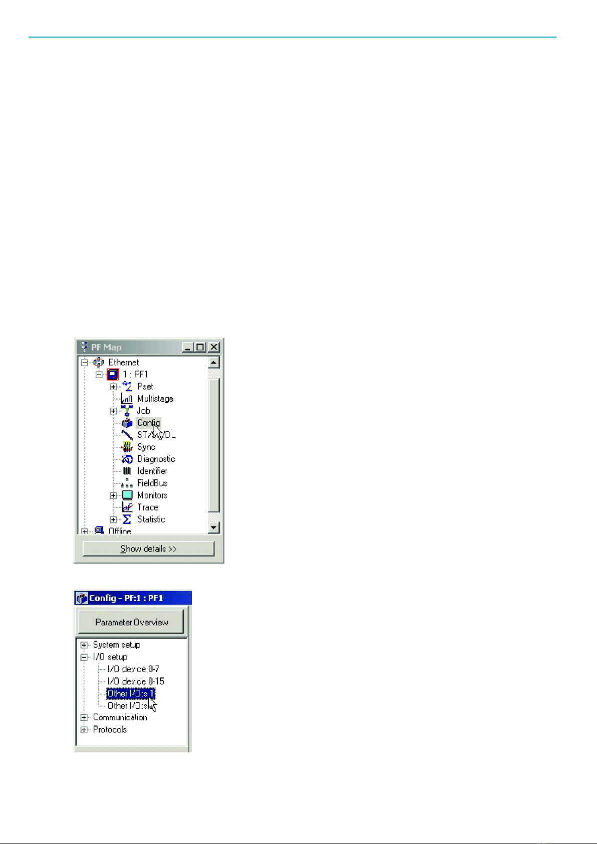
3. In the PF Map; double click Config.
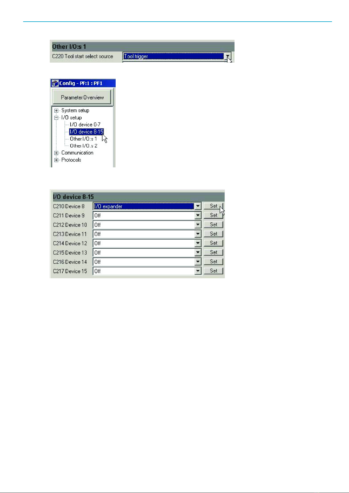
4. In the Config project tree, select Other I/O:s 1.
5. Select Tool trigger for option Tool start select source.
Stacklight ESL-04 EN
© Atlas Copco Industrial Technique AB - 9836 2642 01 5
6. In the Config project tree, select I/O device 8-15.
7. Select I/O expander on the item list for Device 8 and click the Set button to access Relay and Digital
input setup dialog.
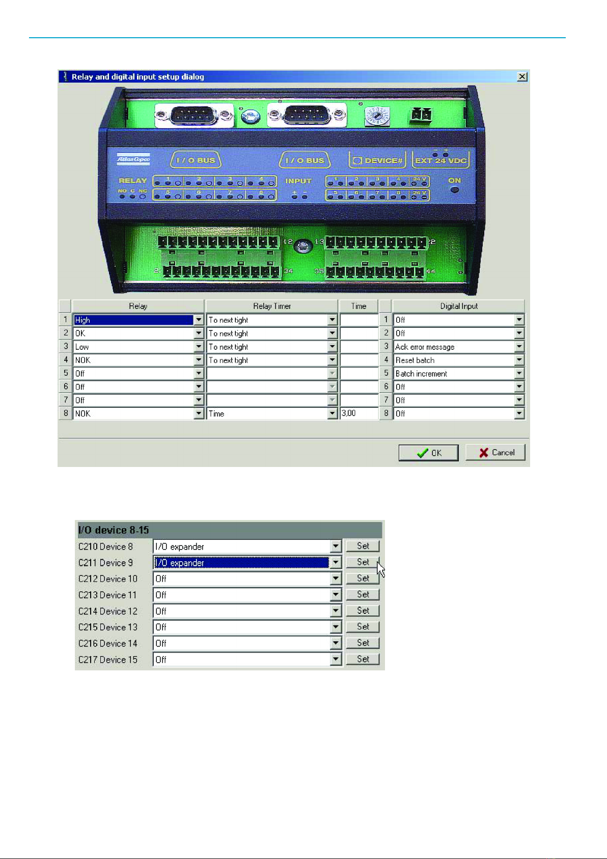
Assign signal variables to stacklight channels by selecting one from each item list.
To obtain the example setup shown in the figure below, assign the following:
1. High to relay output 1, connected to Stack lamp 1.
2. OK to relay output 2, connected to Stack lamp 2.
3. Low to relay output 3, connected to Stack lamp 3.
4. NOK to relay output 4, connected to Stack lamp 4.
5. NOK to relay output 8, connected to the Buzzer. Input 3 in its Time duration box.
6. Ack error message to digital input 3, connected to the left key switch state.
7. Reset batch to digital input 4, connected to the right key switch state.
8. Batch increment for digital input 5, connected to the push button. Then click OK.
EN Stacklight ESL-04
6© Atlas Copco Industrial Technique AB - 9836 2642 01
To complete the setup, do the following:
■Select I/O expander for option Device 9 and click Set to access the Relay and Digital Input setup
dialog box.
Continue to assign signal variables to stacklight channels by selecting one from each item list.
To obtain the example setup shown in the figure below, do the following:
1. Assign Tool locked to relay output 1, connected to the buzzer.
2. Set Relay Timer to Tracking event in its item list for to relay output 1.
3. Click OK and then Store to save settings.
4. Close the Relay and Digital Input setup dialog box to complete the setup session.
Stacklight ESL-04 EN
© Atlas Copco Industrial Technique AB - 9836 2642 01 7
NOTICE The user guide for the tightening controller includes a detailed parameter list of valid signals.
DS or DL Advanced Drive example setup
Stacklight ESL-04 is configured as one I/O device for communication with the DS Advanced drive or the
DL Advanced Drive.
The table shows an example mapping of inputs and outputs for Stacklight ESL-04 with either a Power Fo-
cus or a Pulsor Focus controller. Configuration involves hardware settings and a software setup in the At-
las Copco software ToolsTalk DS/DL.
The Tensor DS and Tensor DL drive has a reduced number of available external inputs and outputs in
comparison to Power Focus, Pulsor Focus and PowerMACS. Therefore some functions are missing
An indicator lamp or stack lamp uses one output. A switch uses two inputs. If a two-way switch is used,
then A1/B1 represents the left switch state and A2/B2 the right switch state. When a push button or one-
way switch is used it is enough to configure A1/B1. It is possible to use both outputs for different functions.
I/O device 1:
Relay Stacklight ESL-04 part Input Stacklight ESL-04 part
1 Stack lamp [1] 1 External input 1 [D]
2 Stack lamp [2] 2 External input 2 [D]
3 Stack lamp [3] 3 Switch state [A1]
4 Stack lamp [4] 4 Switch state [A2]
5 Stack lamp [5] (optional) 5 Switch state [B1]
6 External output 1 [C] 6 Switch state [B2]
7 External output 2 [C] 7 Not used
8 Buzzer [E] (sound 1) 8 Not used
NOTICE Ensure that the Communication Mode switch is set for Tensor controllers. See Hardware set-up.
Ensure that the Address switch is set for Tensor controllers. See Hardware set-up.
EN Stacklight ESL-04
8© Atlas Copco Industrial Technique AB - 9836 2642 01
ToolsTalk DS/DL configuration example
This section includes a step-by-step instruction on how to setup a Stacklight ESL-04 standard ESL-04
with:
■Stack lamp 1 indicating tightening result with high torque.
■Stack lamp 2 indicating an okay (OK) tightening result.
■Stack lamp 3 indicating tightening result with low torque.
■Stack lamp 4 indicating a tightening result that is not okay (NOK).
■The push button used for acknowledging of events.
■The key switch used for batch increment and to reset batch.
■The buzzer sound alerting on an unacceptable tightening.
1. Connect Stacklight ESL-04 to the drive by using the I/O bus cable.
2. Open ToolsTalk and connect the tightening controller.
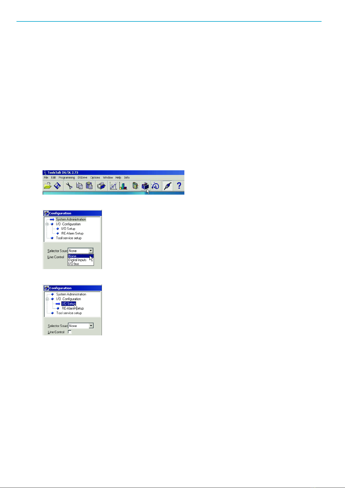
3. In the menu, click on the Configuration symbol.
4. In the Configuration window, select None for option Selector Source.
5. Open the I/O Setup section under I/O-Configuration in the configuration tree window.
Access the configuration dialog box for I/O Expander.
Assign signal variables to stacklight channels by selecting one from each item list. To obtain the example
setup shown in the figure below, assign the following:
1. Ack Error for digital input 3 connected to the push button.
2. Batch increment for digital input 5 connected to the left key switch state.
3. Reset batch for digital input 6 connected to the right key switch state.
4. High Torque to relay output 1 connected to Stack lamp 1.
5. OK to relay output 2 connected to Stack lamp 2.
6. Low to relay output 3 connected to Stack lamp 3.
7. NOK to relay output 4 connected to Stack lamp 4.
8. NOK to relay output 8 connected to the Buzzer.
9. Set Relay Time to three seconds. Click Store and close dialog boxes to complete the software config-
uration.
Stacklight ESL-04 EN
© Atlas Copco Industrial Technique AB - 9836 2642 01 9
NOTICE The user guide for the tightening controller includes a detailed parameter list of valid signals.
PowerMACS example setup
Stacklight ESL-04 is configured as one I/O device with 8 inputs and 16 outputs for PowerMACS communi-
cation. The configuration is made via the Atlas Copco software WinTC.
NOTICE Ensure that the Communication Mode switch is set for PowerMACS. See Hardware set-up. En-
sure that the Address switch is set on a valid address for PowerMACS. See Hardware set-up.
Tthe table below shows an example mapping of inputs and outputs for Stacklight ESL-04 with Power-
MACS.
A light/lamp uses one output and the switch uses two inputs. If a two-way switch is used, then [x1] (where
“x” is the switch position) represents the left switch state and [x2] the right switch state. When a push but-
ton or one-way switch is used it is enough to configure [x1] (but it is possible to use both outputs for differ-
ent functions).
I/O device 1:
Input address Stacklight ESL-04 part Output address Stacklight ESL-04 part
600.0 External input 1 [D] 800.0 Stack lamp [1]
601.0 External input 2 [D] 801.0 Stack lamp [2]
602.0 Switch state [A1] 802.0 Stack lamp [3]
603.0 Switch state [A2] 803.0 Stack lamp [4]
604.0 Switch state [B1] 804.0 Stack lamp [5] (optional)
605.0 Switch state [B2] 805.0 Lamp [A]
606.0 Not used 806.0 Lamp [B]
607.0 Not used 807.0 Buzzer sound 1 [E]
EN Stacklight ESL-04
10 © Atlas Copco Industrial Technique AB - 9836 2642 01
Input address Stacklight ESL-04 part Output address Stacklight ESL-04 part
608.0 Not used 808.0 Buzzer sound 2 [E]
609.0 Not used 809.0 External output 1 [C]
610.0 Not used 810.0 External output 2 [C]
611.0 Not used 811.0 Not used
612.0 Not used 812.0 Not used
613.0 Not used 813.0 Not used
614.0 Not used 814.0 Not used
615.0 Not used 815.0 Not used
WinTC configuration example
This section includes a step-by-step instruction on how to setup a Stacklight ESL-04 standard ESL-04
with:
■Stack lamp 1 indicating tightening result with high torque
■Stack lamp 2 indicating an okay (OK) tightening result
■Stack lamp 3 indicating tightening result with low torque
■Stack lamp 3 indicating the Running signal from the controller
■Stack lamp 4 indicating a tightening result that is not okay (NOK)
■The push button used as light test button
■The buzzer sound alerting on a tightening result that is not okay
1. Connect Stacklight ESL-04 to the PowerMACS controller with a MACS I/O cable.
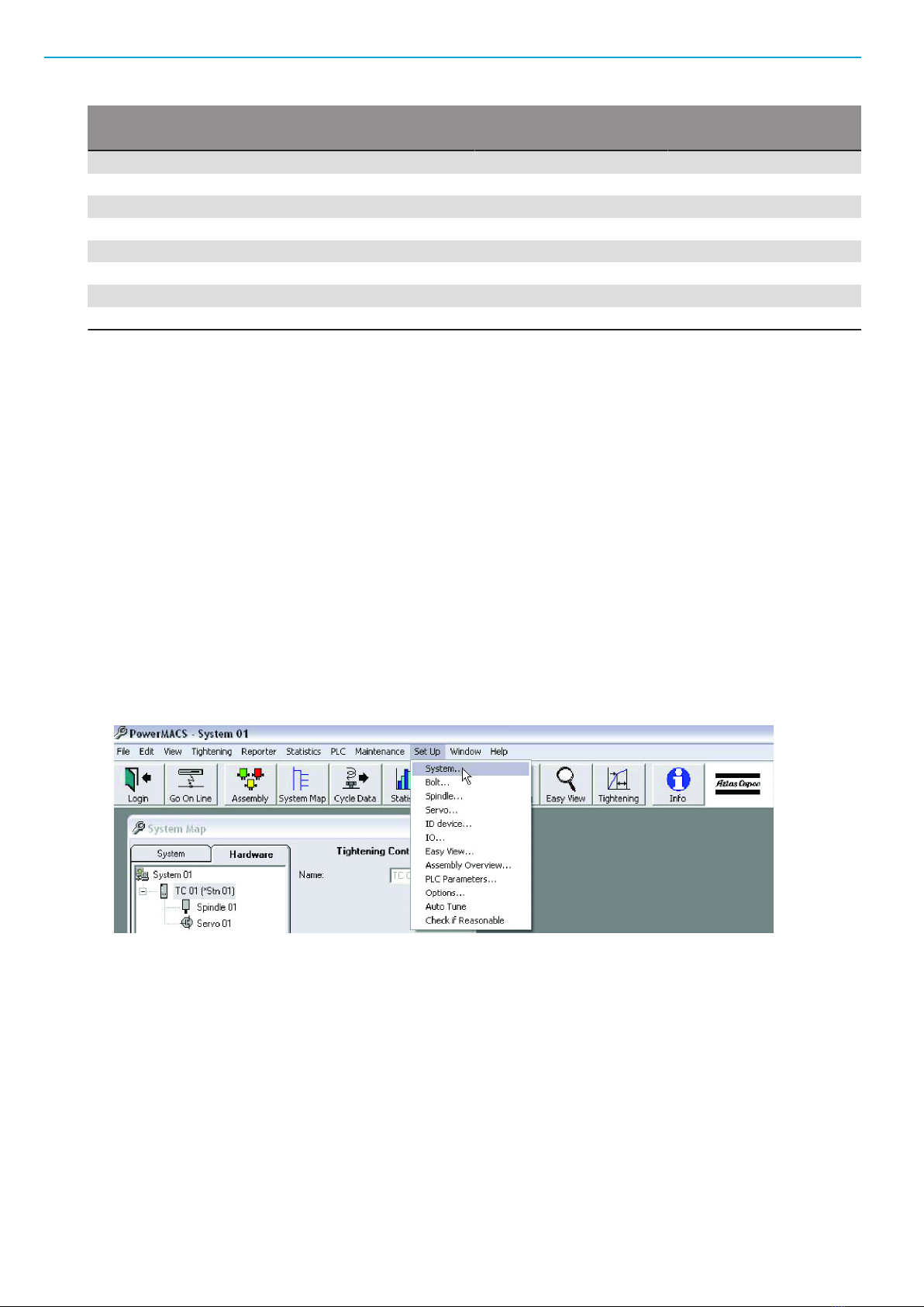
2. Open WinTC and connect PowerMACS.
3. Click Go On Line in the WinTC tool bar.
4. In the Set Up menu, select System.
5. Click Go Off Line in the WinTC tool bar.
6. The System Set Up window appears.
Table des matières
Autres manuels Atlas Copco Équipement d'éclairage

Atlas Copco
Atlas Copco HiLight V2+ Manuel utilisateur

Atlas Copco
Atlas Copco HiLight B6+ Kd ESF Mode d'emploi

Atlas Copco
Atlas Copco QLT H40 Manuel utilisateur

Atlas Copco
Atlas Copco HiLight E2+ESF Manuel utilisateur

Atlas Copco
Atlas Copco HiLight H5+ Hd ESF Manuel utilisateur

Atlas Copco
Atlas Copco HiLight H6+ Kd ESF Manuel utilisateur
Manuels Équipement d'éclairage populaires d'autres marques


Qazqa
Qazqa Suplux SL 3 Black 103062 Manuel utilisateur

Commercial Electric
Commercial Electric 54568141 Manuel utilisateur

CREE LIGHTING
CREE LIGHTING 304 Series Manuel utilisateur

Goobay
Goobay 49867 Manuel utilisateur

ECOMAN ITALIA
ECOMAN ITALIA LED T8 Manuel utilisateur

Alkalite
Alkalite Krypton KT-81 Manuel utilisateur


