ATI Technologies AOV Manuel utilisateur


Manual, AOV Media Changer System
Document #9610-50-1046-02
Pinnacle Park • 1031 Goodworth Drive •Apex, NC 27539 • Tel: +1.919.772.0115 • Fax: +1.919.772.8259 • www.ati-ia.com
2
Table of Contents
1. Product Overview..................................................................................................................... 3
1.1 Media Feeder .................................................................................................................................3
1.2 Media Remover..............................................................................................................................4
1.3 Media Checker...............................................................................................................................4
2. Installation of Components..................................................................................................... 5
2.1 Media Feeder Installation .............................................................................................................6
2.2 Media Remover Installation..........................................................................................................7
2.3 Media Checker Installation...........................................................................................................8
2.4 Pneumatics....................................................................................................................................9
2.5 Electrical Connections..................................................................................................................9
2.5.1 PNP Type Sensor...............................................................................................................9
2.5.2 NPN Type Sensor...............................................................................................................9
3. Operation ................................................................................................................................ 10
3.1 Recommended Sequence of Operations for AMC ................................................................... 11
3.1.1 Recommendations ........................................................................................................... 11
3.1.2 Fetch Media...................................................................................................................... 11
3.1.3 Check Media ....................................................................................................................15
3.1.4 Sand.................................................................................................................................17
3.1.5 Remove Media.................................................................................................................17
3.2 Normal Operation........................................................................................................................19
4. Troubleshooting and Service Procedures ........................................................................... 20
4.1 Troubleshooting..........................................................................................................................20
4.2 Service Intervals..........................................................................................................................21
4.3 Service Procedures.....................................................................................................................22
4.3.1 Replacement of Retaining Gasket, Constant Force Springs, and Media Support Glides in
Media Feeder...................................................................................................................22
4.3.2 Replacement of Hook Disc on Media Checker.................................................................27
4.3.3 Replacement of Needles in Media Remover....................................................................27
5. Serviceable Parts ................................................................................................................... 28
Manual, AOV Media Changer System
Document #9610-50-1046-02
Pinnacle Park • 1031 Goodworth Drive •Apex, NC 27539 • Tel: +1.919.772.0115 • Fax: +1.919.772.8259 • www.ati-ia.com
3
1. Product Overview
The AOV Media Changer (AMC) is an accessory to the AOV tools. TheAMC works with standard industrial
sanding disc and allow for adaptation to changing assembly lines and part requirements.
The AMC system allows the checking and changing of media without human interaction, once a
program is in place.
For drawings and further details, refer to https://www.ati‑ia.com/Products/deburr/deburring_home.aspx.
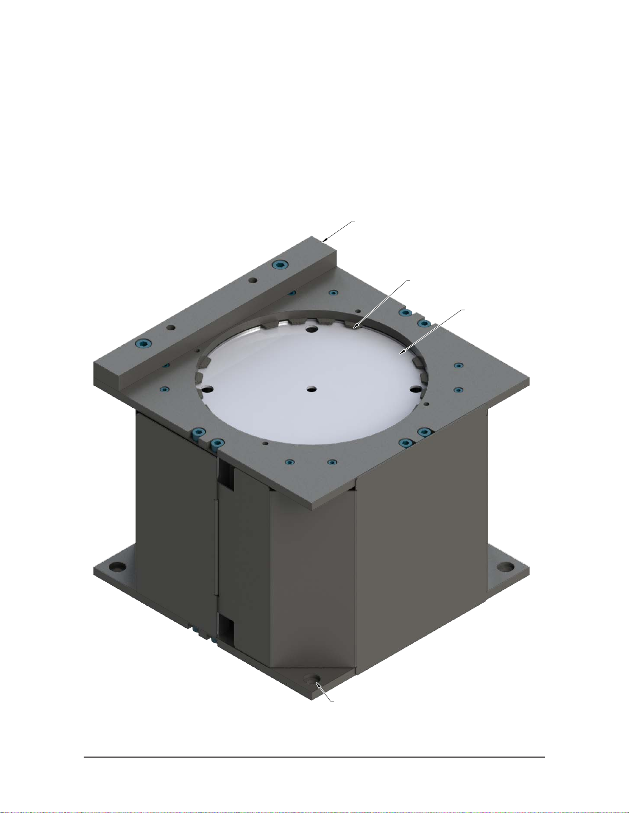
1.1 Media Feeder
The media feeder provides a storage location and dispenser for 5 inch or 6 inch sanding discs.
Figure 1.1—Media Feeder (6” Version Shown)
Alignment Rail
Media Storage
Media Retaining Gasket
(4) Mounting Hole

Manual, AOV Media Changer System
Document #9610-50-1046-02
Pinnacle Park • 1031 Goodworth Drive •Apex, NC 27539 • Tel: +1.919.772.0115 • Fax: +1.919.772.8259 • www.ati-ia.com
4
1.2 Media Remover
CAUTION: Needles can pinch or puncture clothing and skin avoid contact during
setup, service, and operation of needle grippers causing injury to personnel and
damage to equipment.
The media remover uses pneumatically actuated needles to remove media from AOV.
Figure 1.2—Media Remover (Not a Recommended Mounting Orientation)
Mounting Bracket
(7) Mounting Holes Provided
Needle Gripper
4 mm Push Tube Fitting (Extend)
4 mm Push Tube Fitting (Retract)
Needle Height Adjustment
1.3 Media Checker
The media checker detects the presence or absence of sanding media.
Figure 1.3—Media Checker
Sensor cable with 3-pin M8 connector
Media Detection Piston
(4) Mounting Hole
(connector not shown)

Manual, AOV Media Changer System
Document #9610-50-1046-02
Pinnacle Park • 1031 Goodworth Drive •Apex, NC 27539 • Tel: +1.919.772.0115 • Fax: +1.919.772.8259 • www.ati-ia.com
5
2. Installation of Components
Required Equipment:
The items listed in this section are the minimum requirements to operate the AMC.
1. (2) 4 mm air lines in for media remover. Each air line will supply air to the Media Remover and operate the
needle drive mechanism.
• One line is for needle extension.
• One line is for needle retracting.
• The lines will need to purge when switching over from extend to retract or vice versa. See following section
for recommended equipment.
2. (1) 3‑pin M8 connector for media detection. This cable will be used to connect the Media Checker to I/O on the
robot.
Recommended Optional Equipment:
The items listed in the following section are only recommended equipment that can help refine the media change
out process. These are not necessary to operate theAMC.
1. (2) Programmable regulator
• One will be used to adjust the compliance pressure during the operation. Not necessary, but it makes fetching
new media a little easier.
• The other will be used in conjunction with a solenoid valve to control the needle gripper.
2. (1) 4 or 5 position solenoid valve
• This solenoid is used to switch and purge the air between the extend and retract air ports in
the Media Remover.

Manual, AOV Media Changer System
Document #9610-50-1046-02
Pinnacle Park • 1031 Goodworth Drive •Apex, NC 27539 • Tel: +1.919.772.0115 • Fax: +1.919.772.8259 • www.ati-ia.com
6
2.1 Media Feeder Installation
The media feeder can be installed at any an angle and in any orientation that allows the AOV sanding pad to
contact the media in the feeder completely. To install the media feeder, complete the following procedure:
Tools required: Hex keys
Supplies required: (4) Customer supplied socket head cap screws
1. Mount the media feeder to a rigid surface using the (4) mounting holes in the bottom plate with customer
supplied socket head cap screws.
2. Load the feeder by inserting small stacks (15‑25 discs) of media into the storage opening with the hook
and loop side facing outward.
Figure 2.1—Media Feeder
Alignment Rail
Media Storage
Media Retaining Gasket
(4) Mounting Hole

Manual, AOV Media Changer System
Document #9610-50-1046-02
Pinnacle Park • 1031 Goodworth Drive •Apex, NC 27539 • Tel: +1.919.772.0115 • Fax: +1.919.772.8259 • www.ati-ia.com
7
2.2 Media Remover Installation
The media remover can be installed at any an angle and in any orientation that allow the media to fall away
from the media remover. Figure 2.2 is shown only for information purpose and is not a recommended
mounting orientation. Customer supplied waste receptacle is advised for removed media. The media
remover can be installed by performing the following procedure:
CAUTION: Needles can pinch or puncture clothing and skin avoid contact during
setup, service, and operation of needle grippers causing injury to personnel and
damage to equipment.
Tools required: Hex keys
Supplies required: (3 or 4) Customer supplied fasteners
1. Mount the media remover to a rigid surface using either of the mounting patterns on the bracket with
customer supplied fasteners.
2. Connect air supply to the (2) push tube fittings.
Figure 2.2—Media Remover (Not a Recommended Mounting Orientation)
Mounting Bracket
(7) Mounting Holes Provided
Needle Gripper
4 mm Push Tube Fitting (Extend)
4 mm Push Tube Fitting (Retract)
Needle Height Adjustment

Manual, AOV Media Changer System
Document #9610-50-1046-02
Pinnacle Park • 1031 Goodworth Drive •Apex, NC 27539 • Tel: +1.919.772.0115 • Fax: +1.919.772.8259 • www.ati-ia.com
8
2.3 Media Checker Installation
The media checker can be installed at any an angle and in any orientation that allow the sanding pad of the
AOV to contact the piston in the checker completely. The media checker can be installed by performing the
following procedure:
Tools required: Hex keys
Supplies required: (4) Customer supplied socket head cap screws
1. Mount the media checker to a rigid surface using the (4) mounting holes with customer supplied socket
head cap screws. Tighten hand tight.
2. Attach the 3‑pin M8 connector on the sensor cable to the customer supplied connection.
Figure 2.3—Media Checker
Sensor cable with 3-pin M8 connector
Media Detection Piston
(4) Mounting Hole
(connector not shown)
Manual, AOV Media Changer System
Document #9610-50-1046-02
Pinnacle Park • 1031 Goodworth Drive •Apex, NC 27539 • Tel: +1.919.772.0115 • Fax: +1.919.772.8259 • www.ati-ia.com
9
2.4 Pneumatics
The air supply should be dry, filtered, and free of oil. A coalescing filter (ATI Part # 9005‑50‑6160 or
equivalent) with elements rated for 5 micron or better is required.
Customer supplied solenoid valves are actuated from the robot or program logic controller by means of a
digital output signal. The extend/retract for the media remover must supply a regulated air supply pressure
of 4.1 bar [60 psi].
2.5 Electrical Connections
The media checker has an integrated sensor.
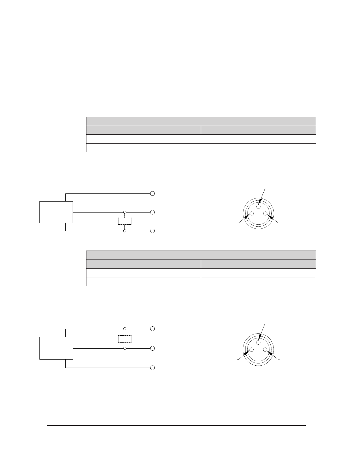
2.5.1 PNP Type Sensor Table 2.1—PNP (Current Sourcing)
Description Value
Voltage Supply Range 10‑30VDC
Output Circuit PNP make function (NO)
Figure 2.4—PNP Type Lock, Unlock and RTL Sensors
(3) Blue
Brown (1)
(4) Black
Brown (1)
Black (4)
Blue (3)
+Vs
Output
0 V
PNP
Z
Connector
PNP (Current Sourcing)
2.5.2 NPN Type Sensor Table 2.2—NPN (Current Sinking)
Description Value
Voltage Supply Range 10‑30VDC
Output Circuit NPN make function (NO)
Figure 2.5—NPN Type Lock, Unlock and RTL Sensors
(3) Blue
Brown (1)
(4) Black
Brown (1)
Black (4)
Blue (3)
+Vs
Output
0 V
NPN
Z
Connector
NPN (Current Sinking)

Manual, AOV Media Changer System
Document #9610-50-1046-02
Pinnacle Park • 1031 Goodworth Drive •Apex, NC 27539 • Tel: +1.919.772.0115 • Fax: +1.919.772.8259 • www.ati-ia.com
10
3. Operation
The media changer system uses (3) different components. The robot program must accommodate for any clearance
needed. Refer to Section 3.1—Recommended Sequence of Operations for AMC for more details.
CAUTION: Do not use spare parts other than original ATI spare parts. Use of spare parts
not supplied by ATI can damage equipment and void the warranty. Always use original
ATI spare parts.
CAUTION: Never be present near the tool while it is in operation. Flying debris can cause
injury. If it is necessary to approach the tool while in motion, stand behind appropriate
Plexiglas windows. Provide a barrier to prohibit people from approaching the tool.
CAUTION: Needles can pinch or puncture clothing and skin avoid contact during
setup, service, and operation of needle grippers causing injury to personnel and
damage to equipment.
Figure 3.1—System
Media Remover
Media Feeder
Media Checker
Table des matières
Autres manuels ATI Technologies Sander


