Astra Navsensor NMEA 2000 Manuel utilisateur
NMEA 2000
Navsensor
User Manual

2

3
Contents
ASTRA Navsensor 4
Preliminary Remarks 4
Safety Instructions for Installation 4
Safety Instructions for Maintenance 6
The ASTRA Navsensor 7
Components 7
Functions 7
The NMEA Interface 8
Installation of the ASTRA Navsensor 10
Flat mount installation 11
Pole mount installation 13
Calibration 14
Diagnostic Indication 17
Hardware Specification 18
Brackets 18
Pinout 18
Technical Data 19
Accessories 21

4
ASTRA
Navsensor
Preliminary Remarks
In purchasing a sensor from the ASTRA marine range you have decided on a
high value product, which has been manufactured according to acknowledged
technical standards. Modern production processes and compliance with
currently applicable quality assurance standards guarantee that our products
leave the factory in perfect condition.
We thank you for making a good choice, and we are convinced that this
instrument will be reliable and of great help to you and keep you safe at sea.
In order to ensure easy and safe handling of your ASTRA sensor, you should
familiarize yourself with all the features and functions.
Please take the time to read these instructions carefully and completely.
Safety Instructions for Installation
This product has been developed, manufactured and tested in accordance
with the requirements of EC, UL and FCC directives and the acknowledged
state of the art.
Please follow all the instructions given in this handbook exactly.
Please pay attention to all text passages labeled with this symbol. These are
very important hints for operating and security of the instruments.
5
Before beginning work the native terminal of the battery
should be disconnected.
Use of information provided by the ASTRA Navsensor does not release
you from the responsibility over your ship and demands good seamanship.
Always use your nautical experience in interpreting the displayed values.
If you carry out this work yourself, wear suitable working clothes. Do not
wear wide fitting clothes. If you have long hair, wear a hair-net. Clothes
and hair can get caught in moving and rotating parts.
Wearing of metallic or conductive jewellery, such as necklaces, bracelets,
rings etc. is not allowed when working on the electrical installation on
board.
Please note that with disconnection of the battery, all volatile electronic
memories lose their input values and must be reprogrammed.
Explosion hazard! Before beginning work on the engine
compartment of petrol engines, switch on the ventilator
of the engine compartment.
Ensure that necessary clearance is provided behind the cable opening, at
the position where the sensor is to be installed.
When selecting the installation position for the sensor, take care that no
stringers are drilled. Be careful also of furniture, floorboards,
superstructure boxes, cables etc.
When carrying out installation work with a sealing compound, solvent
vapours can be formed. Make sure of adequate ventilation and follow the
instructions for use of the sealing compound manufacturer.

6
For the installation only use ASTRA or NMEA approved cables.
If you don’t use standard cables, the wires used should be adequately
insulated or should have sufficient electrical strength, and the contact point
should be protected against electrical shock hazard. The electrical conducting
components of the connected consuming devices should also be protected
against direct contact through suitable measures. Installation of bare metallic
wires and contacts is not allowed.
Take account of the wire cross section. A reduction of the wire cross section
results in a higher current density. This can cause the wire to heat up and
potentially catch fire.
Connect the wires only in accordance to the wiring diagram.
Safety Instructions for Maintenance
The sensor display unit is maintenance-free. Do not use cleaning agents.
Repairs on the sensor should be carried out only by ASTRA authorized
specialists
7
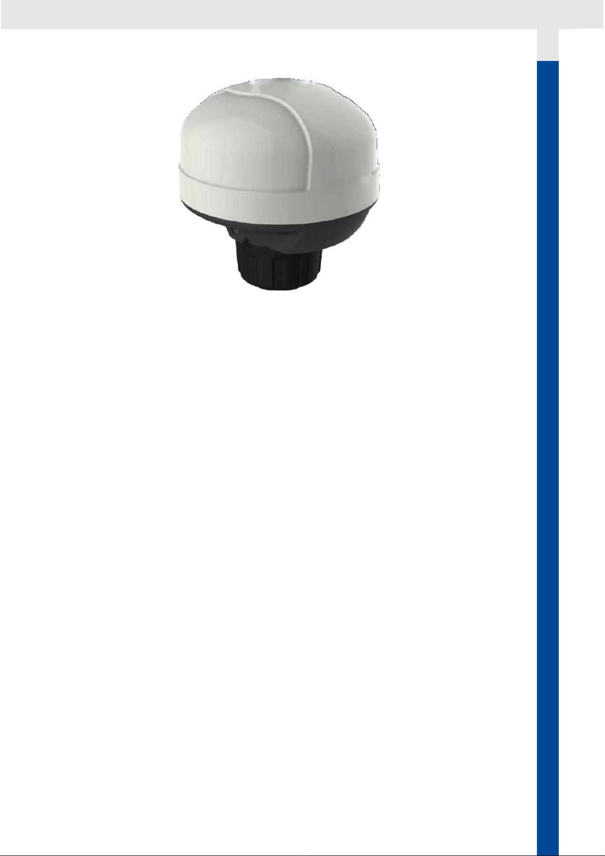
The ASTRA Navsensor
The multifunctional ASTRA Navsensor is the gem of all sensors. The
inertial sensor complements the inbuilt satellite receiver module (GPS)
to provide accurate readings of the speed of travel as well as the pitch &
roll (up and down) and YAW (sideways) motion of the boat. Compass
readings can be displayed electronically thanks to the fluxgate, which
also facilitate course corrections in electronic autopilots.
The barometer and air temperature sensors are early indicators of
forthcoming weather conditions.
Components
In the box:
- Navsensor
- Flat mount bracket
- Pole mount bracket
- Installation instruction
- Mounting screws (not magnetic)
- Warning Sticker
Functions
The sensor provides following information via NMEA 2000:
- GPS-Position
- Date/Time (UTC)
- Speed over Ground
8
- Course over Ground
- Elevation
- Heading
- Barometric Pressure
- Air Temperature
- Rate of Turn
- Pitch and Roll
The NMEA Interface
The ASTRA Navsensor is a NMEA certified sensor. It transmits and receives
NMEA 2000 data to an existing NMEA 2000 network
The parameter group numbers (PGN) of the data which the sensor sends are
given in the table below. More information about NMEA can be found under
www.nmea.org
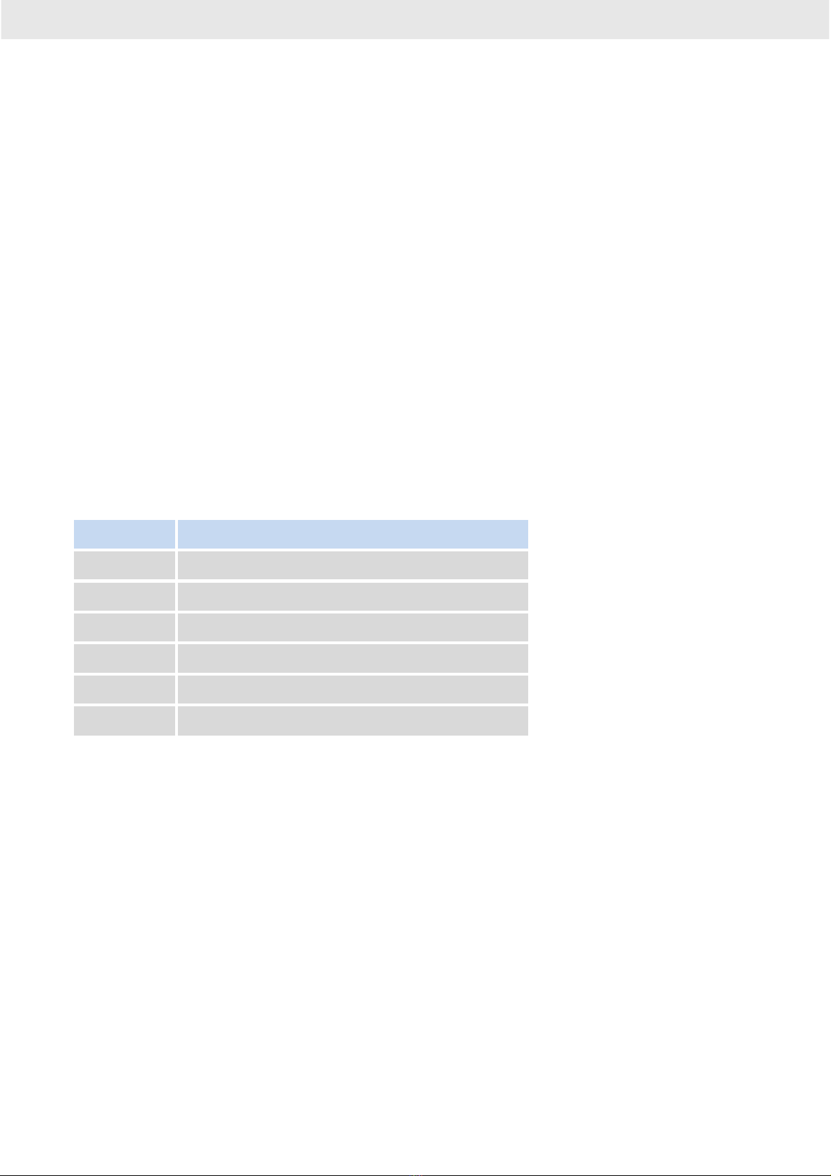
Receiving PGNs
PGN
Message name
59392
Acknowledgment ISO
60928
Address Claim ISO
126208
Command Group Function
59904
Request ISO
60160
Transport Protocol, Data Transfer ISO
60416
Transport Protocol ISO
9
Transmitting PGNs
PGN
Message name
59392
Acknowledgment ISO
60928
Address Claim ISO
65240
Commanded Address ISO
126208
Command Group Function
126464
TX/RX PGN List Group Function
126993
Heartbeat PGN
126996
Product Information
126998
Configuration Information
127250
Vessel Heading
127251
Rate of Turn
127257
Attitude
129025
Position, Rapid Update
129026
COG & SOG, Rapid Update
129029
GNSS Position Data
129033
Local Time Offset
130311
Environmental Parameters
130314
Actual Pressure
130316
Temperature, Extended Range
127258
Temperature (Old Version)
10
Installation of the ASTRA Navsensor
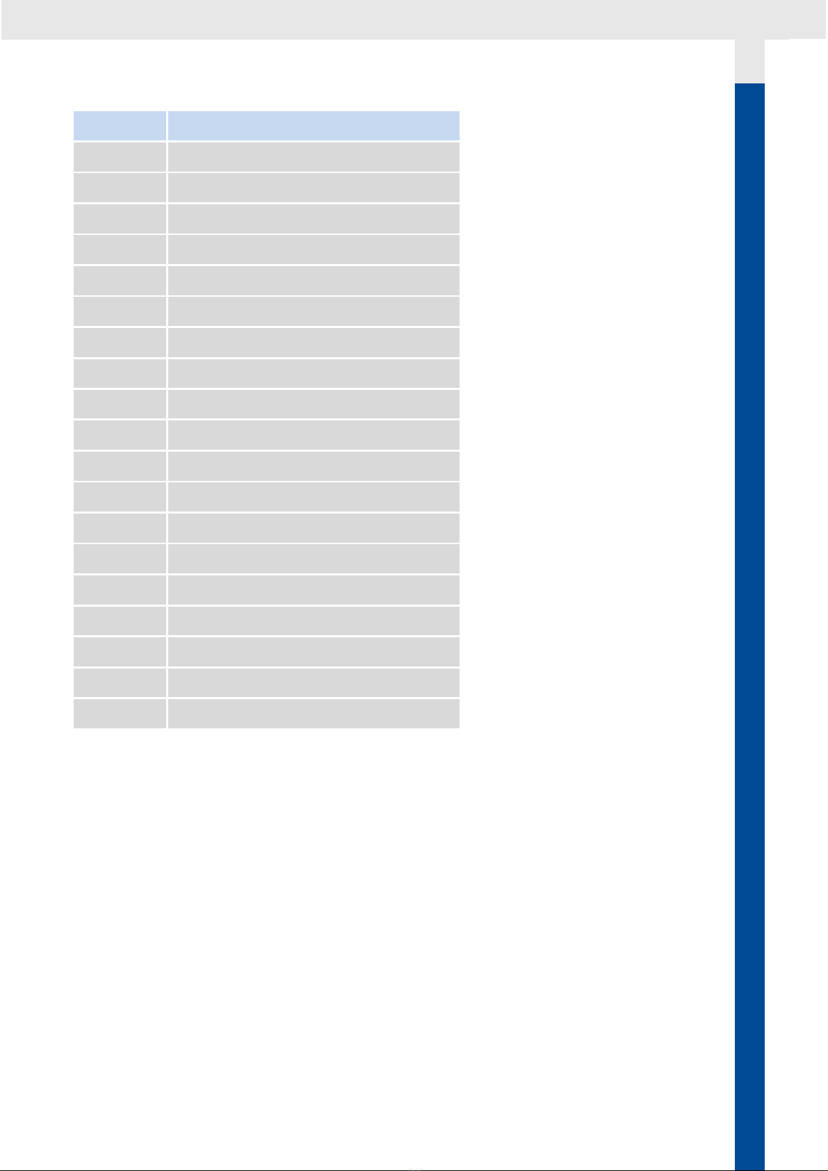
Before beginning, disconnect the negative terminal on the battery, otherwise
you risk a short circuit. If the craft is supplied by auxiliary batteries, you must
also disconnect the negative terminals on these batteries! Short circuits can
cause fires, battery explosions and damages to other electronic systems.
Please note that when you disconnect the battery, all volatile electronic
memories lose their input values and must be reprogrammed.
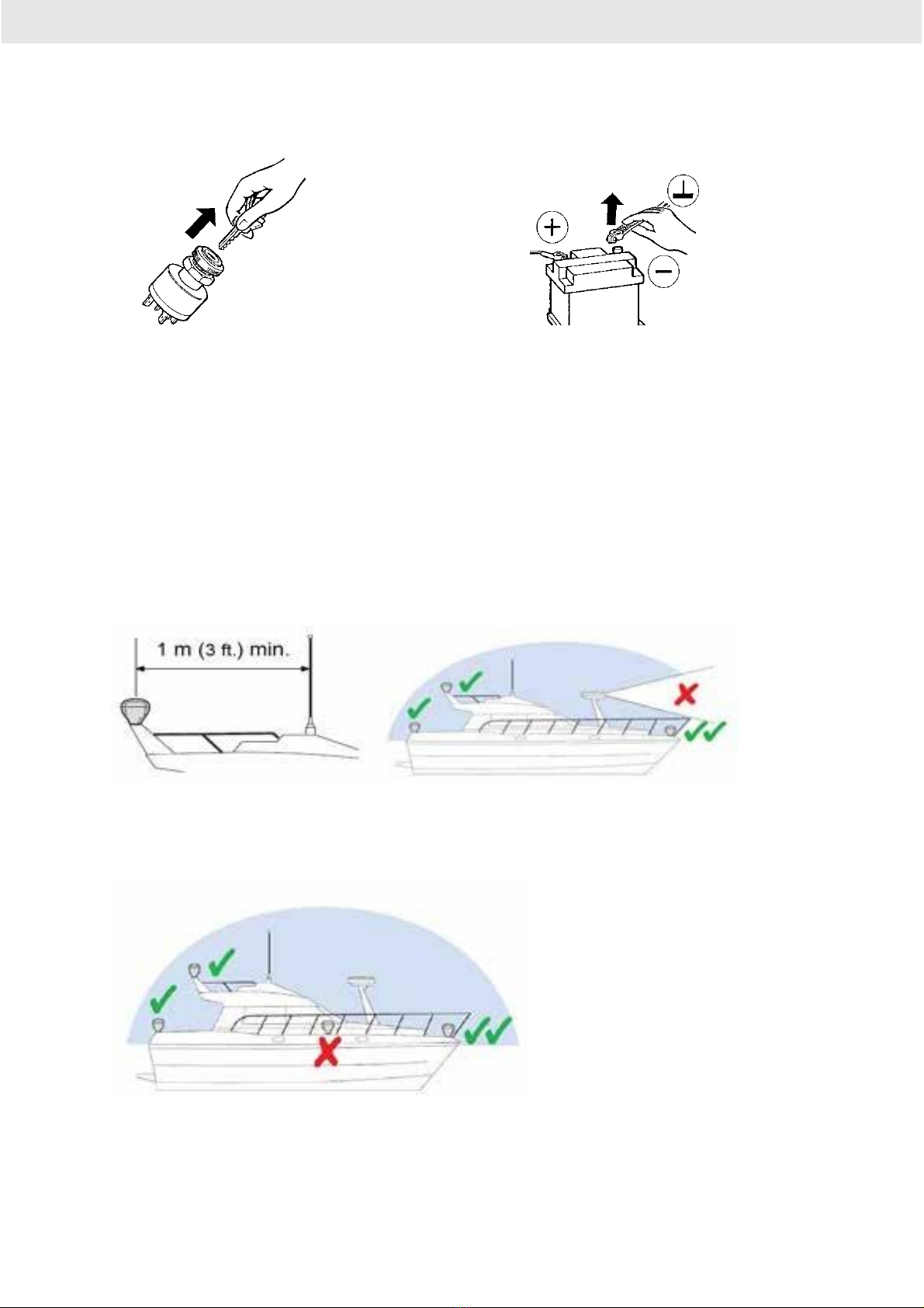
Where to install
Mount the Navsensor at least 1m away from VHF antennas and
clear of radar arrays
Mount the sensor as midship as possible and with clear sky view
Note: If installed on steel hull vessels, install the sensor as high as possible
away from the magnetic steel.
Table des matières


