5
EN
1. NOTES • GUIDELINES • GUARANTEE
1.1. GENERAL SAFETY NOTES
• Observe the notes in these operating instructions!
• Observe applicable statutes and regulations, and the notes in these operating instructions, when handling
hazardous materials
• Observe accident prevention regulations and workplace ordinance
• Ensure that the necessary safety checks are only carried out by authorised sta using original
spare parts
• Only use the hazardous material workplace in a proper condition
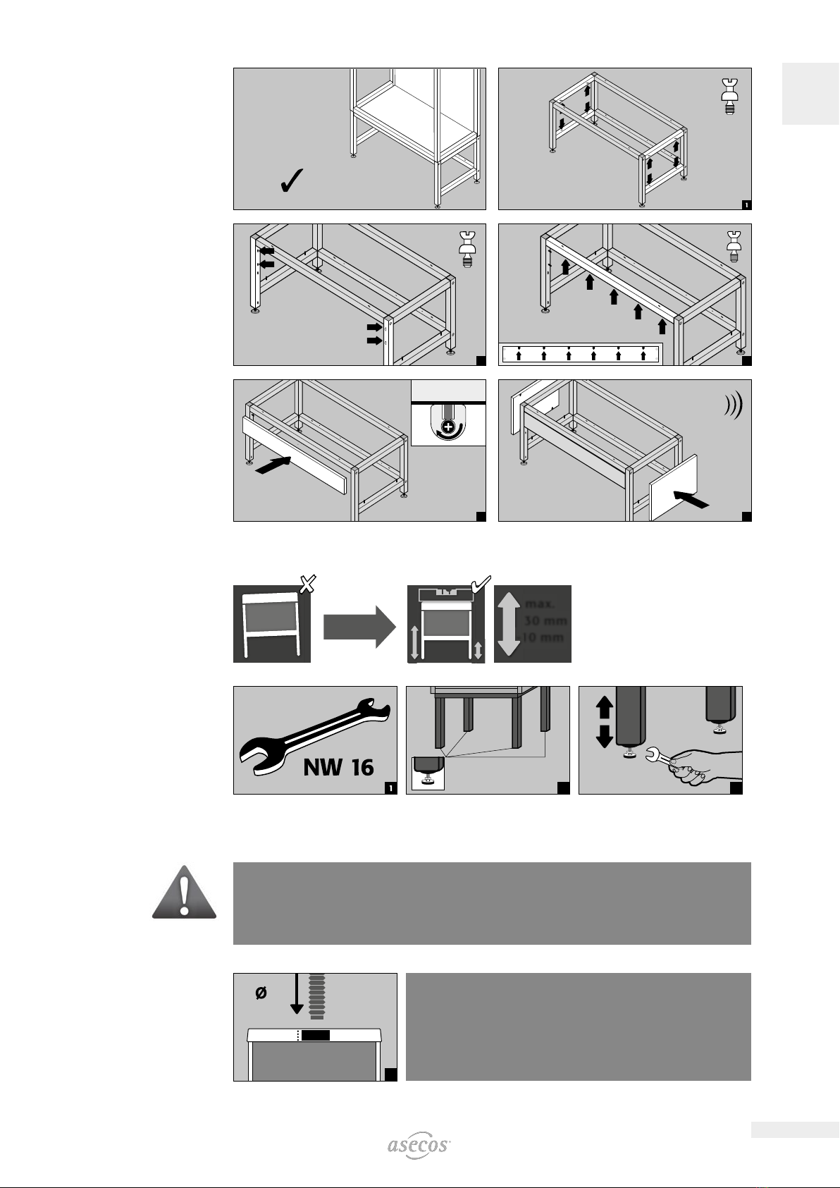
• Make sure that there are no air currents above 0.2 m/s when selecting the place of erection as this can aect
the functional apability.
• The users are to be trained on handling of the hazardous material workplace
• The required exhaust air flow is to be provided on site
• Observe the maximum weight with which the cabin may be loaded
• Any hazardous materials that escape must immediately be collected and removed
• Please check the material resistance of all surfaces for the use of aggressive materials.
• The instructions of the supervisory engineering department must be followed.
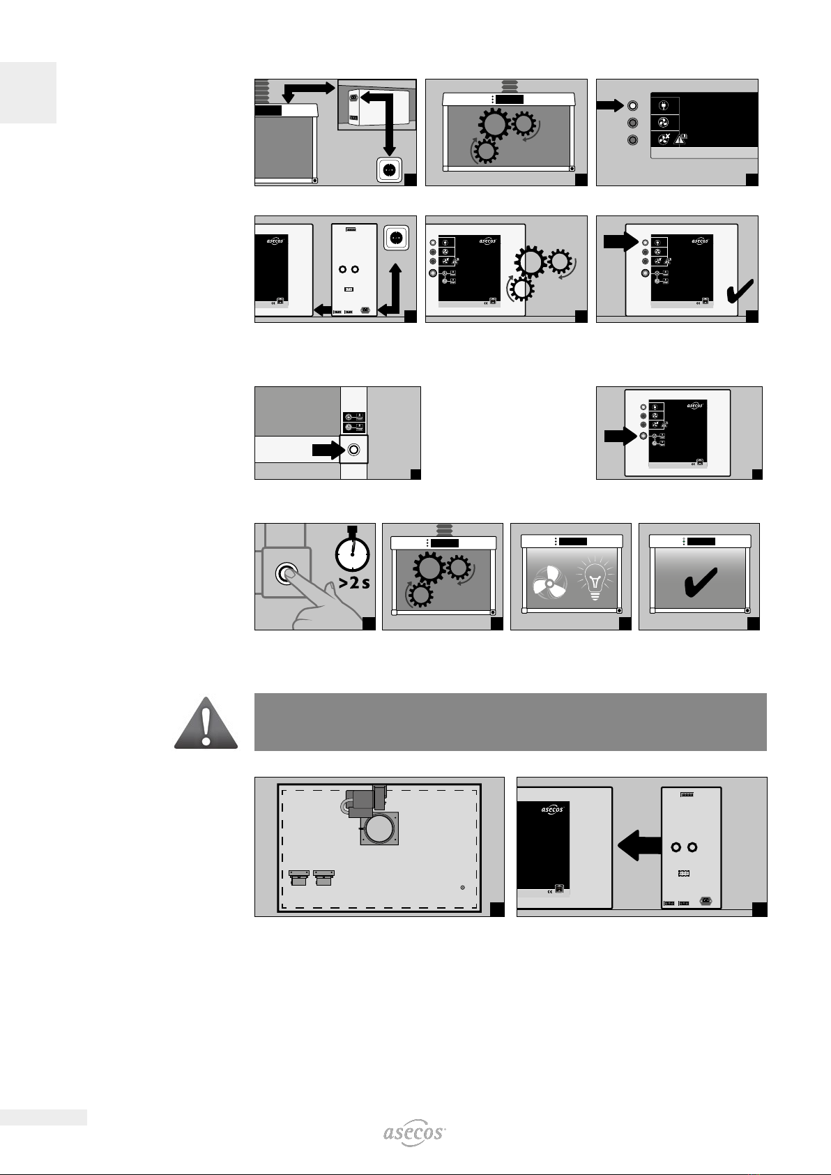
• Elektroinstallationen bzw. Anschlussarbeiten an elektrische Anlagen und Betriebsmittel dürfen nur durch eine
Elektrofachkraft vorgenommen werden.
1.2. GUARANTEE
The warranty for this product is agreed between you (the customer) and your specialist dealer (the seller).
asecos, as the manufacturer, provides a warranty of 24 months from the date of delivery for the products list-
ed in the operating instructions. As a safety device, all models are subject to an annual inspection by specialist
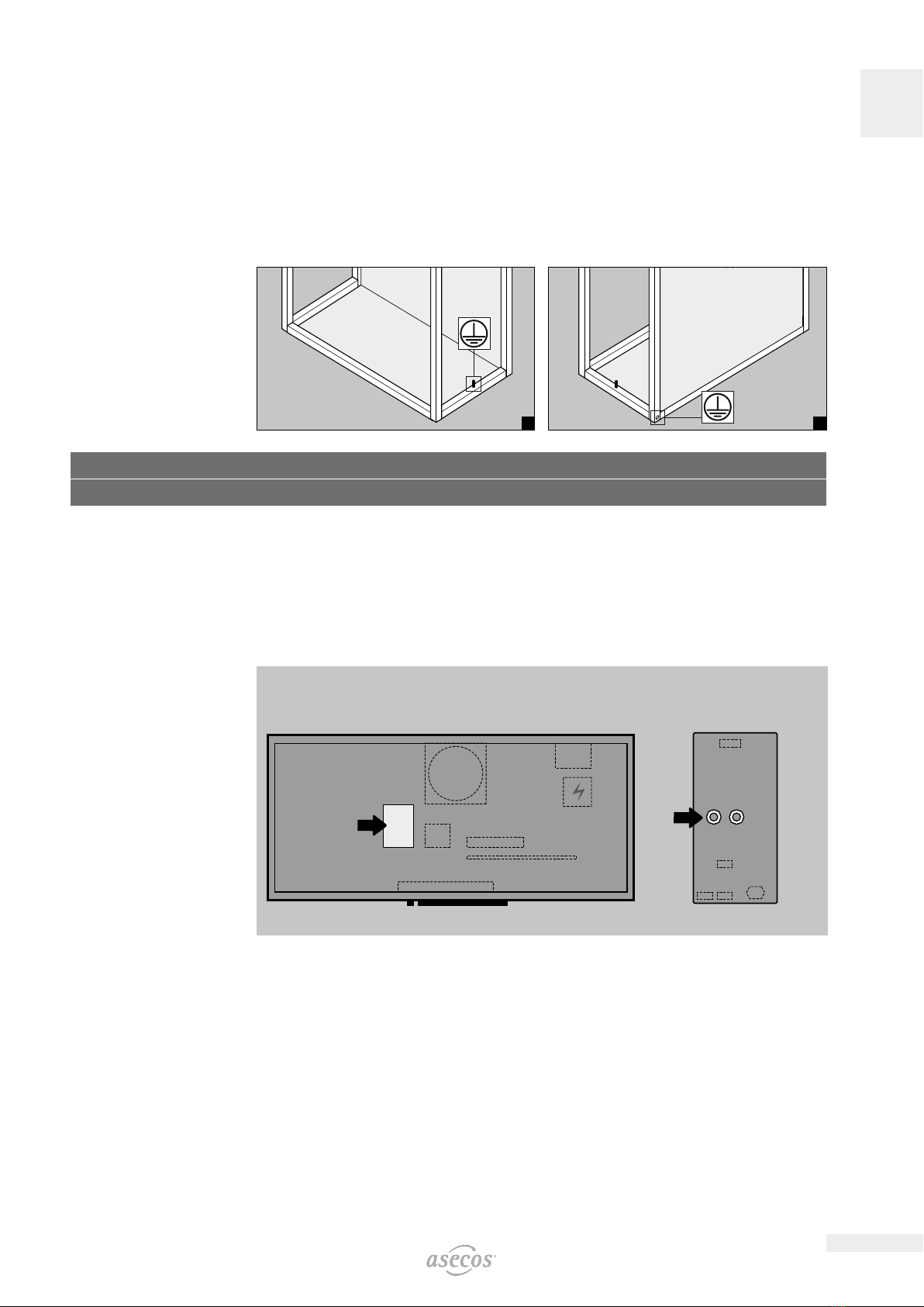
personnel authorised by the manufacturer. All device connections, including electrical and media connections,
must be made exclusively at the transfer points provided by asecos. Failure to do so will invalidate the custom-
er’s warranty claim against the manufacturer.
1.3. DETAILS
Development: asecos GmbH Sicherheit und Umweltschutz, D-63584 Gründau.
Serial No.: inside the hazardous substance workplace on the air duct
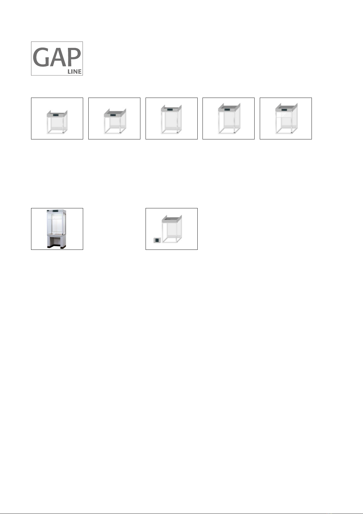
Hazardous material workplace GAP
Complete capture of hazardous vapours, gases or suspended solids at the place where they emerge or where
they are created before they can have eects that are damaging to health or to the environment (see hazard-
ous materialsregulations, workplace regulations and laboratory guidelines)..
Hazardous material workplace GAP
Complete capture of hazardous vapours, gases or suspended solids at the place where they emerge or where
they are created within explosive atmospheres of zone 1, before they can have eects that are damaging
to health or to the environment (see hazardous materials regulations, workplace regulations and laboratory
guidelines).
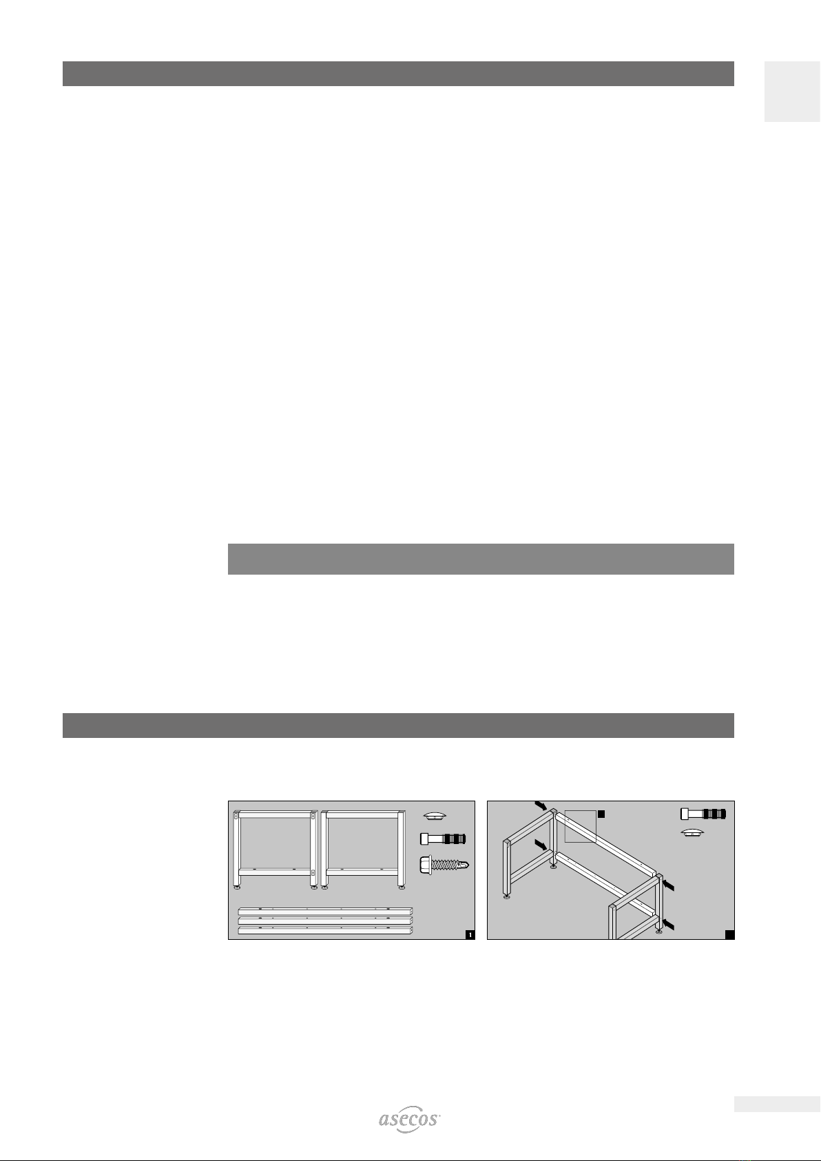
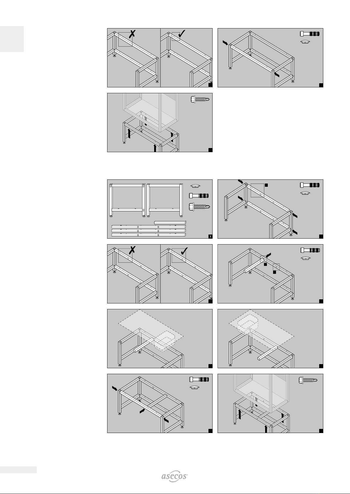
2. ERECTION • COMMISSIONING
2.1. ASSEMBLY OF THE SUPPORT FRAME WIDTH UP TO 1800 MM
6
4
6
4
4
!3