4
RCC 600 SUBWOOFER MODULE (RCC600-SM)
The RCC 600 Subwoofer Module can be installed into either an:
Artison Pre Build Box (Volume ≈1.2 ft3) SOLD SEPERATELY
OR
Infinite Baffle (i.e. 2x4 stud wall, 16” On Center spacing at least 8 feet tall, Volume 2.8 ft3
or greater)
IMPORTANT: In an installation of two RCC600-SM’s that are being powered by one
RCC600-SA, both Subwoofer Modules need to be in either Pre Build Boxes or be in
Infinite Baffles. You cannot connect two RCC 600 Subwoofer Modules that are in
different environments to the same RCC 600 Subwoofer Amplifier.
The front of the RCC600-SM and the grille are paintable. The RCC600-SM comes from the
factory with a paint-shield attached. When painting the RCC600-SM, ONLY paint the grille and
outer edge of the module using the included paint-shield. You will have to tape the shield to the
inside face of the baffle to prevent overspray from getting on the foam damping material on the
face. DO NOT get paint on the rear of the subwoofer module. Paint can damage the
components which would VOID your Warranty.
The minimum mounting depth for the RCC600-SM is 3¾” (95.5 mm), i.e. a 2x4 stud is 3½” deep
add ¼”, ½” or ⅝” thick drywall and the RCC600-SM will fit. The maximum drywall thickness the
RCC600-SM can be mounted in is 1.3125” (33.3 mm).
INSTALLATION WITH AN ARTISON Pre Build BOX (Preferred Installation)
1. Please refer to the Installation Guide included in the Artison Pre-Build Box Carton for
installation instructions for your Artison Pre-Build Box.
2. Using the speaker wire already run inside the Pre-Build Box manage both the positive and
negative conductors through the open tie-wraps on each side of the RCC600-SM.
3. Connect the bare speaker wire ends to the spring-loaded binding posts, manage the speaker
wire back, tighten the tie-wraps and trim the excess.
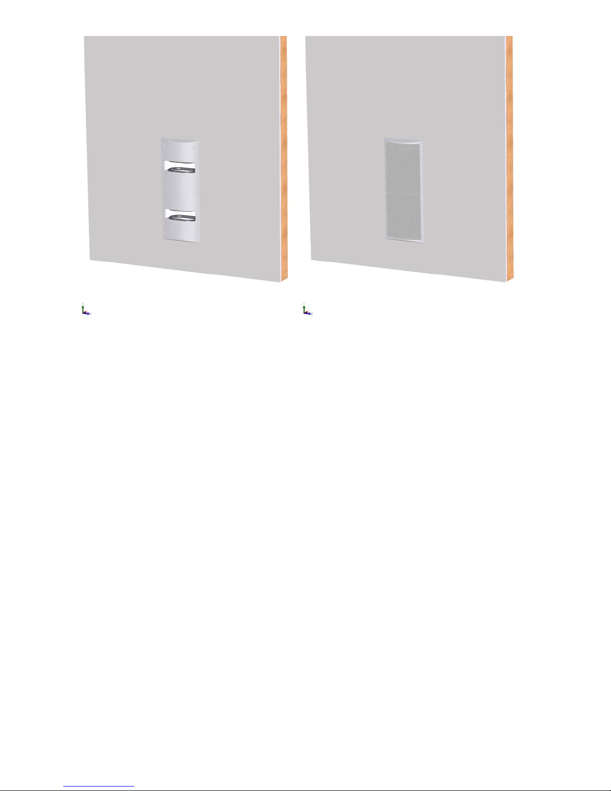
4. Install the RCC600-SM into the pre-cut opening of the Pre-Build Box. See Figure 1.
5. Carefully tighten the six dog leg clamps on the RCC600-SM using the supplied Allen Head
wrench.
6. The grille for the RCC600-SM is held in place by magnets. Simply position the grille on the
front of the module into the recessed area. See Figure 2.
NOTE: While installing the subwoofer module make sure that any excess wire is run